Dolos Device
A low-cost Raspberry Pi false-emitter for home-station EW and SIGINT training.
Overview
There are many ways which this device can be utilized besides its false emitter intent; including: retransmission, jammer, and DF kit. Utilizing a Raspberry Pi and some knowledge in coding, the possibilities are only limited by your imagination. In this configuration, the device and attached devices are unclassified and therefore pose a lower security risk if compromised. It is not recommended that this device hold any information that could be exploited if compromised. Full disk encryption could be used but it would only serve to protect the data at rest and would require the device be unlocked prior to any script execution (the device would not be fully functional when power is applied). Less complexity in design and program configuration allows anyone at the end user level to emplace the device.
Bill of Materials
The following is the parts list for the device.
Core
| Part | Spec | Notes |
|---|---|---|
| Raspberry Pi Zero 2 W | Quad-core, onboard 2.4 GHz Wi-Fi / BLE, ~0.4 W idle | Runs the access point on its own radio. The GPIO header is unpopulated. |
| 2×20 stacking GPIO header | Extended / stacking 40-pin | Soldered to the Pi to seat the LTE Base HAT and keep the UART pins reachable for the optional BFoxCon serial link. |
| microSD card | 16 GB or larger, A1/A2 | Holds the OS and scripts. |
Cellular & timing
| Part | Spec | Notes |
|---|---|---|
| Sixfab 3G–4G/LTE Base HAT | 40-pin HAT, holds a mini-PCIe modem | The carrier board from the Sixfab LTE-M Cellular IoT Kit. |
| Telit ME910C1-WW modem | LTE-M (Cat-M1) + NB-IoT, integrated GNSS | Cellular link and GPS timing in one mini-PCIe module. |
| LTE / GNSS dual u.FL antenna | 100 mm | One lead cellular, one GNSS. |
| Sixfab SIM | LTE-M / NB-IoT data | Ships with the kit. A 90° micro-USB cable carries the modem's data to the Pi's USB port. |
Radio & emitter
| Part | Spec | Notes |
|---|---|---|
| Baofeng UV-5R | Dual-band 2–8 W HT, Kenwood 2-pin SP/MIC jack | The transmitter. |
| Byonics BFoxCon (v1.6) | PIC16F1827 fox-hunt controller; +, −, G, R, P, T pads | Mounts on the radio's back. Keys PTT and plays the tone / Morse sequence; DTMF remote control; runs off the radio battery. |
| UV-5R earpiece / mic headset | Sacrificial, ~$1 | Cut for its 2-pin SP/MIC plug and four wires, soldered to G/R/P/T (see the soldering section). |
Power, enclosure & consumables
| Part | Spec | Notes |
|---|---|---|
| PiSugar 3 (Zero) | Li-ion UPS, pogo-pin mount, RTC, up to 3 A | Powers the Pi from the back contacts, so it never touches the 40-pin header. Its clock retains time. |
| Logic-level MOSFET / load switch | small N-FET or load-switch IC | A Pi GPIO switches the BFoxCon's power on J2 pin 3, so the Pi can power-cycle it. |
| Waterproof case | Conduit box or Pelican-style | Antennas mount externally. |
| Mounting hardware | Assorted M2.5 standoffs, screws, nuts | Holds the boards and keeps the insides from shifting. |
| Wire & heat-shrink | 22 AWG, various colors | For the BFoxCon, headset, and power leads. |
Two halves. BFoxCon + UV-5R is the emitter. Battery-powered, DTMF-controlled, no Pi needed. The Pi Zero 2 W adds the LTE-M and Wi-Fi signatures and orchestration, optionally over the BFoxCon J2 header (1 GND / 2 Serial-In / 3 +3–5 V / 4 Serial-Out). On the Pi, the Base HAT uses GPIO 27/22/6/13/19/26 + UART; the PiSugar sits off-header on the back pogo pins.
Estimated cost
Approximate 2026 prices in USD, before shipping and tax. The Sixfab line is the LTE-M Cellular IoT Kit (Base HAT, Telit modem, antenna, and SIM together).
| Item | Approx. |
|---|---|
| Raspberry Pi Zero 2 W | $15 |
| microSD card | $8 |
| Stacking header | $3 |
| Sixfab LTE-M Cellular IoT Kit | $80 |
| Baofeng UV-5R | $30 |
| Byonics BFoxCon (assembled) | $63 |
| Sacrificial headset | $2 |
| PiSugar 3 | $40 |
| Case, hardware, wire | $25 |
| Total | ~$265 |
Tools and Supplies Required
- Soldering Iron and associated kit
- Wire strippers
- Precision screwdriver set (attaching boards together and wires to terminals)
- Shrink tubing
- 22 AWG wire (various colors)
- USB to micro USB cables (quantity will vary per components used)
- Multimeter
Radio Interface · BFoxCon + UV-5R
The BFoxCon ships assembled and pre-wired to the radio side: the G/R/P/T pads are factory-wired to a 2-pin SP/MIC plug, and the +/− pads to a power lead for the BL-5L extended battery. You plug it in, you don't solder.
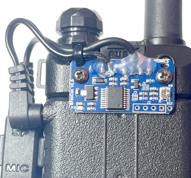
How it's wired (reference)
The factory wiring follows the manual's SP/MIC pad table. You won't touch these pads on the assembled board, but it helps to know what each one carries:
| Plug contact | Function | BFoxCon pad |
|---|---|---|
| 2.5 mm sleeve | Ground | G |
| 2.5 mm tip | Receive Audio | R |
| 3.5 mm sleeve | Push-To-Talk | P |
| 3.5 mm ring | Transmit Audio | T |
| BL-5L battery jack | +7.4 V | + |
| (via SP/MIC plug) | Ground | − |
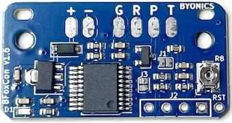
If you bought the unassembled PCB instead, you solder these G/R/P/T wires yourself: cut a UV-5R headset, ohm out the four leads, and solder each to the top of its pad.
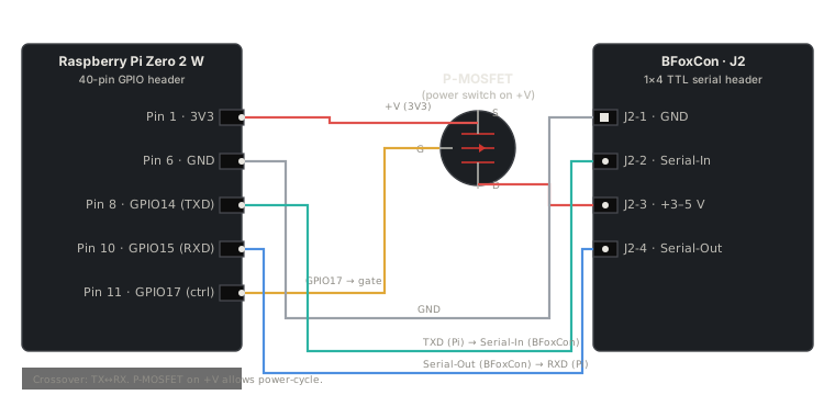
Pi → BFoxCon (J2 serial)
This is where the Pi takes control. The Pi connects to the BFoxCon's J2 serial header (the 1×4 row of pads near RST). The Pi powers the BFoxCon through J2 pin 3 (so it can power-cycle to re-enter the 3-second config window), and writes configuration over UART.
J2 pinout (from the BFoxCon manual)
| J2 pin | Function | Pi pin | Pi function |
|---|---|---|---|
| 1 (square) | Ground | Pin 6 | GND |
| 2 | Serial In | Pin 8 | GPIO14 / TXD |
| 3 | +3–5 V | Pin 1 | 3V3 (switched by a GPIO + MOSFET) |
| 4 | Serial Out | Pin 10 | GPIO15 / RXD |
Serial is crossed: the BFoxCon's Serial-In takes the Pi's transmit (TXD → J2 pin 2), and the BFoxCon's Serial-Out feeds the Pi's receive (J2 pin 4 → RXD).
Wiring diagram
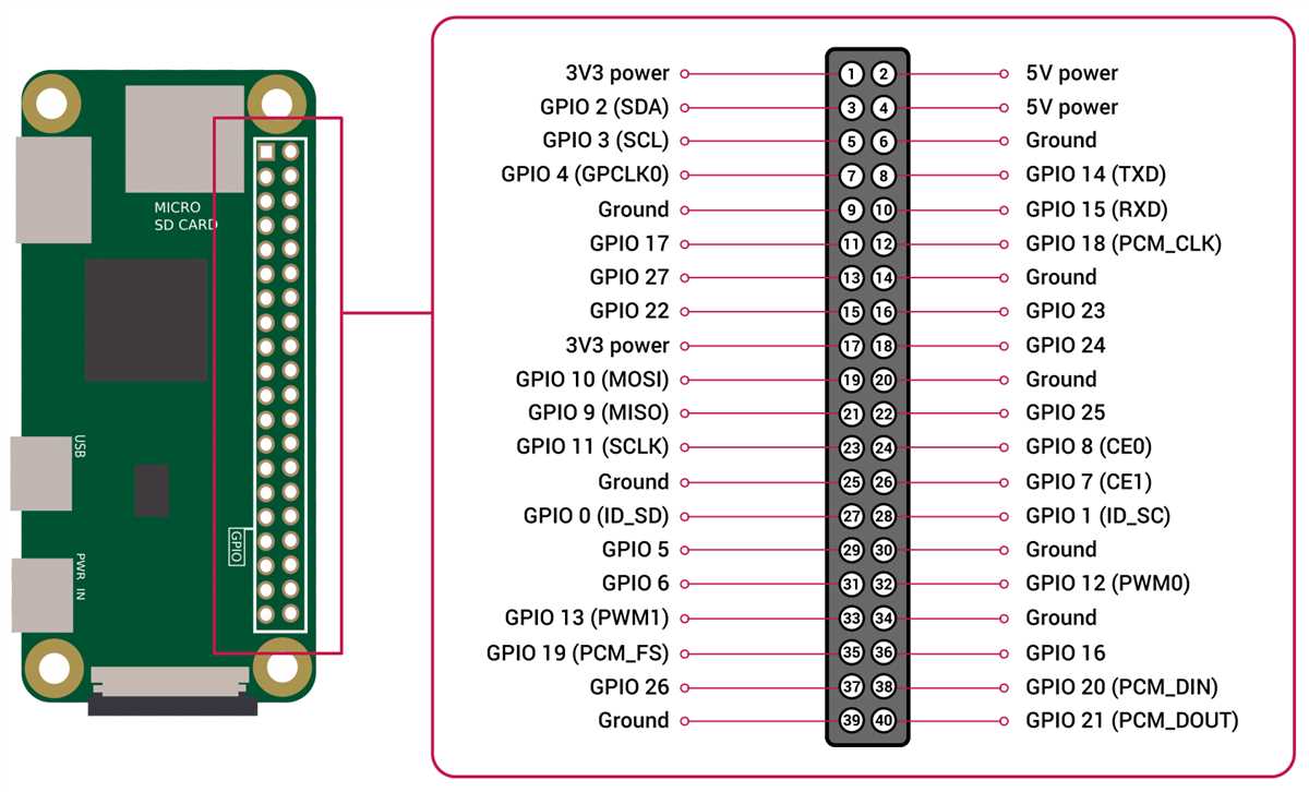
Pi pinout reference
Why the MOSFET, why the 3-second window
Two facts from the BFoxCon manual shape this design: configuration only works in the first three seconds after the BFoxCon powers up, and on a serial cable it will not run until it gets the first serial command. So the Pi powers the BFoxCon through a GPIO-controlled MOSFET on J2 pin 3. Drop the GPIO low to kill power, drive it high again to start a fresh boot, and write configuration inside that 3-second window.
The BL-5L power lead (the factory +/− wiring) is only for running the BFoxCon standalone with no Pi. Under Pi control, power the BFoxCon from the Pi through J2 pin 3 instead. Otherwise you have two supplies fighting.
The assembled BFoxCon ships with a USB-to-TTL serial config cable. The TTL side ends in a 1×4 J2 plug. Cut off the USB end (that's where the USB-serial converter chip lives), ohm out the four wires back to the J2 plug pins (1 GND / 2 In / 3 +V / 4 Out. Colors are not universal, so verify), and solder them to the Pi at the corresponding pins. That gives you a clean removable connection at the BFoxCon end with permanent solder at the Pi end.
Soldering
On the assembled build, the BFoxCon is already wired. The only soldering you do is the Pi's GPIO header (the Pi Zero 2 W ships with bare GPIO pads) and the four wires from the cut-down BFoxCon config cable to the Pi.
Solder the 2×20 stacking header to the Pi
- Seat the header square on the Pi's GPIO pads.
- Tack two opposite corner pins to hold it in place.
- Flip the board, check it sits flat and perpendicular.
- Solder all 40 pins, about a second of iron contact each, clean joints with no bridges between adjacent pins.
A stacking (extended) header lets the LTE Base HAT seat on top while leaving the UART pins (8 and 10) reachable underneath for the BFoxCon J2 link.
Solder the Pi end of the BFoxCon config cable
- Cut the USB end off the BFoxCon config cable.
- Strip and tin each of the four wires.
- Ohm them out against the J2 plug pins (1 GND / 2 In / 3 +V / 4 Out) so you know which wire is which.
- Solder them to the Pi: GND → pin 6, In → pin 8 (TXD), +V → through your MOSFET to pin 1 (3V3), Out → pin 10 (RXD).
- Heat-shrink each joint.
Dolos Build
The Pi stack assembles top-down: solder the stacking header to the Pi, clip the PiSugar 3 onto the Pi's back pogo pins, insert the Telit ME910C1 into the Sixfab Base HAT, seat the Base HAT onto the Pi's stacking header, then attach the LTE/GNSS antenna and run a USB cable from the Base HAT to the Pi's USB port. The Bill of Materials lists every part with its product link.
Mount the Raspberry Pi, power module, radio interface, and associated plugs and accessories in the waterproof case you intend to use. Set it in a way that prides easy access to any power switches and ports for recharging the battery, also set it in a way to prevent the insides from shifting about during deployment and potentially breaking connections. Antennas should be mounted externally and oriented to allow efficient and correct wave propagation. It is advised to test connectivity and functionality of the device prior to mounting inside the case. It is also advised to utilize an onboard time retention module or GPS timing module if it is your intent to utilize the device for “on time” effects.
Capabilities & Triggers
The finished device is triggered and controlled three ways. Each path can start, stop, and reconfigure the emitter; the two data paths also run commands on the Pi.
| Trigger | Path | What it does |
|---|---|---|
| Radio (DTMF) | UV-5R receive → BFoxCon | Start / stop / toggle transmit and change tones, timing, and the Morse ID over the air. No data link needed. |
| Wi-Fi | Pi access point | Join the AP and SSH to the Pi: full shell, swap audio and configs, drive the BFoxCon over its J2 serial. |
| Cellular (LTE-M) | Telit modem → mesh VPN | SSH and run commands from anywhere over the Headscale/Tailscale mesh; small data back. |
All three reach the same two things: the Pi (shell and scripts) and the BFoxCon (DTMF or J2 serial).
A fleet, and sensors
These deploy as a fleet. Build several, emplace them across an area, and a team hunts them like live SIGINT targets. Each Pi joins the mesh under its own hostname (dolos-1, dolos-2, …), so you command any node from one place.
The Pi has spare GPIO once the Base HAT and the J2 link are wired. Attach sensors. Motion, door, vibration. And the dolos tool reads them and reports over the mesh. A sensor event can also trigger the emitter, so a node fires when something trips it.
Operating System
Raspberry Pi OS Lite (64-bit), Bookworm, flashed with Raspberry Pi Imager 2.0. The wizard sets everything for a headless first boot.
- Choose Device: Raspberry Pi Zero 2 W.
- Choose OS: Raspberry Pi OS Lite (64-bit).
- Choose Storage: the microSD.
- OS customization: hostname
dolos; usernameuser; enable SSH with your public key; set Wi-Fi for first boot; set locale. - Write, boot, then
ssh user@dolos.localandsudo apt update && sudo apt full-upgrade -y.
Access Point
Bookworm uses NetworkManager. Hostapd and dnsmasq are not used and will conflict if installed. One command stands up the AP on the onboard radio.
nmcli device wifi hotspot ifname wlan0 ssid dolos password CHANGEME
nmcli connection modify Hotspot connection.autoconnect yes ipv4.method sharedwlan0 serves the AP, so it is not also a Wi-Fi client. Field updates come over the cellular link instead.
Cellular Link (LTE-M)
The Telit ME910C1 on the Base HAT connects to the Pi by USB. On Bookworm, ModemManager manages the modem and NetworkManager brings up the connection. No ttyS0, minicom, or PPP scripts.
- Insert the SIM, connect the LTE/GNSS antenna, and seat the Base HAT; run the 90° micro-USB lead to the Pi's USB port.
- Confirm the modem is seen:
mmcli -L. - Create the connection:
nmcli con add type gsm ifname '*' con-name dolos-lte apn YOUR_APN connection.autoconnect yes. - Verify:
mmcli -m 0andip addr show wwan0.
LTE-M is low-bandwidth and sits behind carrier NAT. Right for command and control, not streaming. APN and Telit specifics: Sixfab Base HAT docs.
Boot & Autostart
rc.local is removed in Bookworm. NetworkManager autostarts the AP and the cellular link; run any orchestration script as a systemd service.
# /etc/systemd/system/dolos.service
[Unit]
Description=Dolos orchestration
After=network-online.target
Wants=network-online.target

[Service]
ExecStart=/home/user/dolos.sh
Restart=always

[Install]
WantedBy=multi-user.target
sudo systemctl enable --now dolos.service
journalctl -u dolos -fSoftware · the dolos tool
The network services (access point, LTE-M, mesh) run from config and autostart. One thin Python tool, dolos, is the control surface; run it over SSH from the Wi-Fi AP or the mesh.
| Command | Does |
|---|---|
| dolos status | LTE link, GNSS fix, PiSugar battery, tailnet, AP clients |
| dolos fox start | stop | Switches BFoxCon power (its auto-start flag means power = run) |
| dolos fox set --id CALL --loop MIN | Power-cycles the BFoxCon and writes config over J2 serial |
| dolos beacon | Pushes a GNSS / status report back over the mesh |
BFoxCon link
A Pi GPIO drives a MOSFET on the BFoxCon + line to power-cycle it; the Pi UART (GPIO14/15, reached through the stacking header. The Base HAT leaves UART disconnected) talks to J2 (pin 2 Serial-In, pin 4 Serial-Out, pin 1 GND). Config is accepted only in the first three seconds after power-up, so set power-cycles, then writes.
The BFoxCon J2 baud and command framing are not printed in the manual. Read them off the byonics.com/mfconfig WebSerial tool and confirm against the board; the skeleton's serial writes are placeholders until then. Also set enable_uart=1 and free the serial console so the Pi's PL011 UART is on GPIO14/15.
Skeleton
#!/usr/bin/env python3 # dolos. Dolos control tool. Run over SSH (Wi-Fi or the mesh). Import argparse, subprocess, time, serial import RPi.GPIO as GPIO FOX_PWR = 17 # GPIO -> MOSFET on the BFoxCon + line PORT, BAUD = "/dev/serial0", 115200 # baud/framing: confirm against the BFoxCon def power(on): GPIO.setmode(GPIO.BCM); GPIO.setup(FOX_PWR, GPIO.OUT); GPIO.output(FOX_PWR, on) def fox_set(callsign, loop_min): power(False); time.sleep(1); power(True) # power-cycle for the 3 s config window with serial.Serial(PORT, BAUD, timeout=1) as s: s.write(b"***\r") # enter config (MicroFox family) s.write(f"C1 {callsign} #\r".encode()) # Morse ID (encoding: confirm vs MFConfig) s.write(f"A3{loop_min:02d}00\r".encode()) # loop time mm:ss def status(): print(subprocess.getoutput("mmcli -m 0 | grep -i state")) # LTE link print(subprocess.getoutput("tailscale status | head -1")) # mesh # add: GNSS fix, PiSugar battery over I2C p = argparse.ArgumentParser(prog="dolos") sub = p.add_subparsers(dest="cmd") sub.add_parser("status") f = sub.add_parser("fox"); f.add_argument("action", choices=["start","stop","set"]) f.add_argument("--id"); f.add_argument("--loop", type=int, default=10) a = p.parse_args() if a.cmd == "status": status() elif a.cmd == "fox": if a.action == "start": power(True) elif a.action == "stop": power(False) elif a.action == "set": fox_set(a.id, a.loop)Remote Command & Control
The three trigger paths converge on the Pi and the BFoxCon. The 2018 IFTTT and Dropbox callback is gone; the mesh VPN reaches the Pi directly.
Over the air (radio)
Send DTMF to the radio: 1 start, 2 toggle, 3 stop, D lock. The A/B/C codes reconfigure tones, timing, and the Morse ID. No Pi needed.
Over Wi-Fi or cellular (shell)
Join the Pi to your mesh, then SSH to it from anywhere. No public IP or port forwarding, which is what makes it work behind carrier NAT.
curl -fsSL https://tailscale.com/install.sh | sh
sudo tailscale up --login-server https://YOUR_HEADSCALE
# then from any node on the mesh:
ssh user@dolos
From the shell, run any command, swap audio and configs, or drive the BFoxCon over its J2 serial within the three-second post-power-up window.
Bring-up & Verification
Bring it up in layers and test each before adding the next, so a failure points at one layer.
- Pi base. Flash Bookworm Lite, boot headless, SSH in, update.
- Networking. Stand up the Wi-Fi AP and the LTE-M link, then join the mesh. Confirm you can SSH the Pi over Wi-Fi and over cellular.
- Radio, standalone. Power the BFoxCon off the BL-5L, set the UV-5R to a ham frequency, set your callsign as the Morse ID; confirm it transmits the loop and IDs, listening on another radio.
- Serial protocol. With a USB-TTL adapter and the byonics.com/mfconfig tool, read and write the BFoxCon to capture its baud and command bytes.
- Pi UART. Set
enable_uart=1, free the serial console, loopback-test/dev/serial0. - Wire J2 to the Pi (TX/RX/GND + the switched power line); confirm the Pi power-cycles the BFoxCon and reads its version back over serial.
- End-to-end. From a node on the mesh, SSH to the Pi over cellular and run
dolosto set the ID, then start and stop the emitter; confirm RF on another radio.
Emplacement, Power & Case
Power budget
Emplaced runtime is battery capacity divided by average draw. The Pi Zero 2 W idles near 0.4 W and the LTE-M link is low-power; the radio's transmit duty cycle is what drains the pack, so the BFoxCon's off-air delays and a low duty cycle buy runtime. Pick a target runtime, size one main battery, and for indefinite emplacement add a small solar panel and charge controller.
Permanent wiring
Solder the J2 link; a friction-fit plug works loose in an emplaced box. The BFoxCon's own config cable is the easy way: cut off the USB end (the converter), ohm out the four TTL leads, and solder them to the Pi. Serial-In to TX (pin 8), Serial-Out to RX (pin 10), GND to pin 6, +V to the Pi's switched 3.3 V line. Power the BFoxCon from the Pi only, not also the BL-5L.
Case
A custom 3D-printed enclosure holds the stack on M2.5 standoffs, mounts the antennas outside (LTE/GNSS and the radio's), and seals to weather with one access/charge port.
UTILITY3D Print CalculatorOPEN →Fleet
Build several, give each a unique hostname, and join them all to the mesh. Spread them across the area for a realistic hunt, and command any node from one console.
Legal & Safety
A licensed amateur operator must run this, and the UV-5R must transmit on an amateur band only. Intentional interference or jamming is illegal; the false-emitter use is for authorized training and foxhunting on amateur frequencies.
47 CFR §97.119: the station must transmit its callsign at the end of each transmission and at least every ten minutes. An automatic CW identifier must not exceed 20 WPM.
Set the BFoxCon Morse ID to your callsign and the loop time to ten minutes or less. That is the built-in identifier.
Every node must identify with your callsign (or assigned IDs), and you coordinate frequencies so the nodes don't interfere with each other or with other users.
Sources
- EW Dolos Device Build Guide, EW Community, September 26, 2018 (Light Fighter Library: Communicate / EW-SIGINT).
- 2026 hardware: Sixfab LTE-M Cellular IoT Kit. Https://sixfab.com/product/raspberry-pi-cellular-iot-kit-lte-m/
- 2026 hardware: Sixfab 3G–4G/LTE Base HAT pinout. Https://docs.sixfab.com/docs/raspberry-pi-3g-4g-lte-base-hat-technical-details
- 2026 hardware: PiSugar 3 (Raspberry Pi Zero UPS, pogo-pin, RTC). Https://docs.pisugar.com/docs/product-wiki/battery/pisugar3/pisugar-3-series
- 2G/3G sunset (justifies the LTE-M move): FCC 3G phase-out. Https://www.fcc.gov/consumers/guides/plan-ahead-phase-out-3g-cellular-networks-and-service ; T-Mobile 2G retirement 2026-08-03. Https://www.t-mobile.com/support/coverage/t-mobile-network-evolution
- https://beebom.com/how-to-run-commands-on-raspberry-pi-by-email/
- https://raspberrypi.stackexchange.com/questions/42753/how-to-use-pi-to-remote-control-a-cell-phone-in-another-country
- https://www.rtl-sdr.com/building-your-own-cell-phone-network-with-a-raspberry-pi-and-bladerf/
- https://mbro95.github.io/PortableCellNetwork/
- https://hristoborisov.com/index.php/projects/turning-the-raspberry-pi-into-a-sms-center-using-python/
- https://pinout.xyz/
- http://www.raspberry-projects.com/pi/command-line/io-pins-command-line/io-pin-control-from-the-command-line
- https://www.raspberrypi.org/products/raspberry-pi-3-model-b-plus/
- https://www.raspberrypi.org/downloads/raspbian/
- https://www.raspberrypi.org/documentation/raspbian/
- https://sixfab.com/product/gsmgprs-shield/
- https://sixfab.com/product/mini-gsm-antenna-1-5dbi/
- https://sixfab.com/product/sma-to-u-fl-rf-adapter-cable-120mm/
- https://www.raspberrypi.org/documentation/configuration/wireless/access-point.md
- Raspberry Pi OS Bookworm Wi-Fi access point with NetworkManager. Https://raspberrytips.com/access-point-setup-raspberry-pi/
- Sixfab Base HAT + Telit module setup. Https://docs.sixfab.com/docs/getting-started-with-base-hat-and-telit-le910c1-module
- Run a program at boot on Bookworm (systemd). Https://raspberry.tips/en/raspberrypi-einsteiger/raspberry-pi-autostart-setup
- Raspberry Pi behind CG-NAT via Tailscale/Headscale. Https://www.jeffgeerling.com/blog/2022/ssh-and-http-raspberry-pi-behind-cg-nat/
- Station identification, 47 CFR §97.119. Https://www.law.cornell.edu/cfr/text/47/97.119
- Byonics BFoxCon Manual v0.4. Https://byonics.com/downloads/BFoxCon_Manual_v0.4.pdf