On this page
Electricity: current, voltage, and resistance
Every part has a rating printed on it, and reading it correctly lets you swap one part for another safely; a misread rating can destroy the part. Those ratings rest on three quantities that run through every circuit in this module: voltage, current, and resistance. This unit takes them one at a time.
Current is the movement of electric charge. Electrons drift through a wire from the negative terminal toward the positive, but by long-standing convention current is treated as flowing the opposite way, from positive to negative, and that convention sets the direction of every arrow and symbol in this module.8 Current is measured in amperes, or amps. One amp is a relatively large amount of current, larger than almost anything built in this course will draw. Therefore, values are typically expressed in milliamps, or thousandths of an amp. An LED, for example, typically operates at approximately 20 mA, while a motor may draw around 250 mA. A sensor in sleep mode may draw only a few microamps, or millionths of an amp. The conversions are straightforward: one amp equals 1000 milliamps, and one milliamp equals 1000 microamps.
Voltage is the force that drives current through a circuit. It creates pressure that pushes charge through a wire, and a higher voltage produces a stronger push. It is important to understand that voltage is never a value that exists at a single point; it is always the difference between two points. As Bartlett explains, "You can actually never measure voltage absolutely."8 For instance, a 9-volt battery does not contain "9 volts" at any single location. Rather, one of its terminals is 9 volts higher in potential than the other. A single alkaline battery cell produces 1.5 volts; when six cells are connected together, their voltages combine to produce 9 volts. Other chemistries run at other voltages; Module 03 covers the 3.7-volt lithium cell. Voltage is measured in volts, denoted by the symbol V.
Resistance opposes the flow of current. Every material exhibits some degree of resistance. As Bartlett states, "Resistance is how much a circuit or device resists the flow of current."8 Copper exhibits very little resistance, which is why it is commonly used in wiring and is classified as a conductor. Plastic exhibits very high resistance and allows almost no current to pass through it. For this reason, wires are often coated in plastic, which is classified as an insulator. Resistance is measured in ohms, denoted by the symbol Ω.
Ohm's law
Suppose you want to power a component from a 9 V battery, but the component will burn out if the current exceeds a certain value. You need a resistor to limit the current, and you need to determine the correct value for that resistor. Ohm's law provides the answer.
Ohm's law relates the three quantities from the previous unit in a single equation. The current through a resistor equals the voltage across it divided by its resistance. Ohm's law is written as I = V / R, where I is the current in amps, V is the voltage in volts, and R is the resistance in ohms.8 This equation expresses in symbols what the previous unit described in words: as resistance increases, current decreases, because a larger number is being divided into the voltage.
Because this equation contains three quantities, knowing any two allows you to calculate the third. Use I = V / R when the voltage and resistance are known and the current is unknown. Use V = I × R when the current and resistance are known and the voltage is unknown. Use R = V / I when the voltage and current are known and the resistance is unknown.
Consider the following example. Given a 12 V source and a 120 Ω resistor, determine the current. Since the voltage and resistance are known, use I = V / R. Dividing 12 by 120 gives 0.1 A, meaning 100 mA flows through the resistor.
The tool below allows you to set the voltage and resistance and observe how the current responds according to the equation.
Interactive Ohm's law Adjust the voltage and the resistance, and read the current the ammeter shows: I = V / R. Open it full screen →Power
You install the correct resistance value, power the board, and the resistor overheats anyway. The resistance value alone never guaranteed the part was safe. A resistor doesn't just limit current; it also converts some of the electrical energy passing through it into heat. If a resistor generates more heat than it can shed, it overheats and fails, and inside a sealed enclosure that heat has nowhere to escape. So before trusting a resistor in a circuit, you need to calculate how much heat it will produce and check that figure against the rating printed on the part.
Power is the rate at which a component converts electrical energy, measured in watts (W).8 In a resistor, that energy all turns into heat. Power tells you how fast heat builds up, and that rate depends on two things together: the voltage across the part and the current through it. Increase either one, and the power increases. This is why resistance alone doesn't tell you whether a resistor is safe: resistance determines the current, but the heat produced depends on voltage and current combined, and a small resistor can only dissipate so much of it.
Every resistor has a maximum power rating: the most power it can convert into heat without being damaged.8 This rating is separate from its resistance value, and the circuit must stay below it or the resistor will overheat and fail.8
The governing formula is power equals voltage times current, written P = V × I, where P is in watts, V is the voltage across the part, and I is the current through it.8 In a fixed resistor, power rises with the square of the current (P = I² × R), so doubling the current quadruples the power, not doubles it.
Take the circuit from the previous unit: 12 V drives 0.1 A through a 120 Ω resistor. Since voltage and current are known, P = V × I = 12 × 0.1 = 1.2 W. The resistor dissipates 1.2 W, meaning it must be able to shed that much heat. A standard through-hole resistor is rated at only 0.25 W, about a fifth of what's needed, so it would overheat.
Do not run a part right at its rated limit. A common rule of thumb is to choose a rating at least twice the power the part will dissipate. Twice 1.2 W is 2.4 W, so you'd select a 3 W resistor, the next standard size up. A part running at half its rated power holds up to heat and long-term use far better than one running at its limit.
Interactive Power dissipation Set the voltage and resistance, read the power the resistor dissipates, then check it against a rating. Open it full screen →The circuit
Every fault on a board traces back to whether the loop is complete. A circuit is a closed loop: current leaves one terminal of the source, passes through every part along the path, and returns to the other terminal. It only flows while that path stays unbroken.
Current is not consumed as it moves through the loop. Whatever amount leaves the source is the same amount that returns to it, and in a single series loop, that amount is the same at every point along the way: a part near the end carries exactly what a part near the start does. This matters because it explains the two most common failures.
Break the loop anywhere (an open switch, a disconnected wire, a bad solder joint) and current stops everywhere in that loop at once, not just at the break. That is why a board can look fully assembled and still do nothing: one open point is enough to stop the whole loop. Give the loop an unobstructed shortcut instead, a bare wire touching straight across the source, and current has nothing left to limit it. Ohm's law from unit two gives the current a single loop carries: I = V / R.8 With almost no resistance in the path, R collapses toward zero and I climbs toward whatever the source can deliver, which is why a short can overheat a board the instant it is powered.
Parts join a loop one of two ways. In series, there is a single path, so every part shares the same current. In parallel, there is more than one path, so current splits between them while the full source voltage appears across each branch.
The tool below lets you see this directly. Switch the loop between working, open, and shorted, click each part, and use the Series and Parallel tabs to watch the paths change. The current reads 23 mA for the working loop, zero once the switch opens, and a damaging 50 A for the bare-wire short.
Interactive Reading a circuit Switch one loop between working, open, and shorted, and click any part to read what it does. Open it full screen →Resistors
You pull a resistor from a bin and find no number on it, only four colored bands. If you misread those bands and install a 100 Ω resistor where the circuit calls for 10 kΩ, a hundred times the intended current flows, which can destroy the part the resistor was meant to protect. The color code lets you read a resistor's value from its bands, and lets you work backward from a required value to the bands you need to find. On a resistor pulled from a salvaged board or an unlabeled bin, the color code is the only way to identify it.
A resistor does not consume current; it limits how much current flows through part of a circuit. That limiting effect is called resistance, measured in ohms (Ω).8 A higher resistance value permits less current at a given voltage; a lower resistance value permits more.
A resistor's body is too small to print numerical digits on, so its value is encoded in colored bands instead. You read the bands in a fixed order starting from one end; reading from the wrong end produces the reversed, incorrect value, so you must orient the resistor correctly before reading it. The tolerance band identifies which end to start from: it is gold or silver, and no digit band is ever gold or silver. Place the gold or silver band on the right, and read the remaining bands from left to right. Many resistors also leave a wider gap between the third band and the tolerance band, but not all manufacturers do this, so use the gold or silver band as the primary indicator and the gap only as a secondary check.

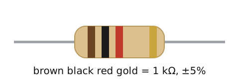
The first two bands represent digits, the third represents the multiplier (the number of zeros to add), and the fourth represents tolerance, how far the actual value may deviate from the marked one: gold indicates ±5%, silver indicates ±10%.8
Consider the resistor shown in the figure above, with bands brown, black, red, gold. First orient the resistor: since gold is a tolerance band, it belongs on the right, meaning you read starting from the brown end. Read the digits: brown represents 1, black represents 0, giving 10. Apply the multiplier: red represents 2, so two zeros are added, turning 10 into 1000. This means the resistor's value is 1000 ohms, written as 1 kΩ, with a tolerance of ±5% indicated by the gold band.
Rare parts below 10 ohms use gold or silver as the third band instead, where it shifts the decimal point down rather than adding zeros.
The tool below shows a new random resistor each time. Read its bands the same way: digits, multiplier, tolerance.
Interactive Resistor color code Read four bands and state the resistor's value, against a full table of colors and positions. Open it full screen →Capacitors
A board that must run reliably needs a steady 5 V supply, and getting there starts with a capacitor. The part bins hold two kinds: small flat discs, and larger cylinders with a stripe down one side. You tell them apart by shape and by the printed value. A flat disc is a ceramic capacitor, and a striped cylinder is an electrolytic. An unsteady supply means noise in a radio receiver and corrupted data in a microcontroller. So the choice of part, and its polarity, decides whether the board works.
A capacitor is two metal plates separated by a thin insulator called the dielectric.8 Because the plates never touch, a steady direct current cannot flow straight through. Put a voltage across the leads and charge builds up on the plates. Charge keeps building until the capacitor reaches that voltage, and then it holds that charge.8 Current flows only while the charge is changing. This means a capacitor blocks direct current and passes alternating current, the kind that keeps reversing.8
Capacitance is how much charge a capacitor stores per volt across it. A bigger capacitance holds more charge at the same voltage. Capacitance is measured in farads (F). One farad is enormous, so real parts are rated in smaller units: microfarads (µF, millionths), nanofarads (nF, billionths), and picofarads (pF, trillionths).8
Two types cover most work, and the value splits them. A ceramic capacitor holds small values, from a few picofarads up to about a microfarad, and is not polarized, which means either lead can go either way. An electrolytic holds large values, from about a microfarad up to thousands. It is polarized: it has a positive lead and a negative lead that must go the right way round. The longer lead is positive and goes to the higher voltage. The striped side is negative and goes to ground. Read that stripe as a plus mark and you wire it backward, and then it can overheat or fail.

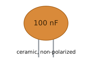

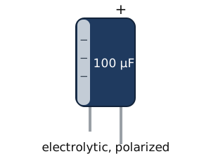
The value is printed on the part, but the two types print it differently. An electrolytic is big enough to carry its full value in plain text on the can. A ceramic is not, so it carries a three-digit code instead: read the first two digits as they are, add as many zeros as the third digit says, and the result is the capacitance in picofarads.8 The most common decoupling capacitor is marked 104: 10 with four zeros added is 100,000 pF, which is 100 nF. A letter after the digits is the tolerance: J is ±5%, K is ±10%, and M is ±20%.8 You sort parts by this code every time you reach into the bin, so read it the way you read a resistor's bands.
The most common job for a capacitor is to steady a supply. The sequence: the supply charges the capacitor, dips for a moment, and the capacitor discharges to fill the gap. The result is a steadier voltage with the noise absorbed. A larger value holds more reserve to fill those dips, so smoothing a rail calls for a large value. A capacitor used this way is called a decoupling or smoothing capacitor.
Every capacitor also carries a working voltage, the most it can take before the dielectric breaks down and the part fails. You pick one rated above the voltage in your circuit, the same check you made against a resistor's power rating.
Interactive Capacitor type and polarity Read a value against the ceramic and electrolytic ranges, then decide whether polarity matters. Open it full screen →Diodes and LEDs
A status LED is the small light that shows a board has power, and it sits on nearly every field device, from a radio to a sensor node. Wire that LED directly to a 5 V supply, and it draws too much current, overheats, and burns out. The fix is a resistor in series, sized to hold the LED's current at a safe level. The same rule sizes any LED on any supply. To size that resistor, you first need the part it protects: the diode.
A diode allows current in one direction and blocks it in the other.8 Its two leads are the anode and the cathode. Current flows from anode to cathode and is blocked in the reverse direction. The triangle in the schematic symbol points in the direction current flows, and the line printed on the diode's body marks the cathode.

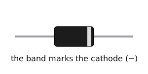
A diode does not conduct at all until the voltage across it reaches its forward voltage. Once the diode turns on, its voltage stays close to that forward voltage even as more current flows through it. A resistor does not behave this way: its voltage keeps rising with current. This means a diode drops a nearly fixed amount of voltage no matter how much current runs through it. A silicon diode drops about 0.7 V once it conducts (sources put it anywhere from 0.6 to 1 V; this module uses 0.7 V throughout). A Schottky diode is a faster type that drops less, about 0.15 to 0.45 V.1 Diodes also convert alternating current into direct current, block a battery wired backward, and absorb the voltage spike a coil produces when it switches off. A diode placed backward across the coil gives that spike a harmless path to circulate through instead of reaching the rest of the circuit. Used this way it is called a flyback, or freewheeling, diode.8
A light-emitting diode, or LED, is a diode that emits light when it conducts. It needs more voltage to turn on than a plain silicon diode (about 1.8 to 2.2 V for a red LED depending on the part, compared to 0.7 V for the diode; this module uses 2.0 V), and that extra energy is released as light.8,1 Like any diode, it passes current in one direction only. On the part, the longer lead is the anode, and a flat spot on one side of the rim marks the cathode.

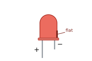
Why does an LED need a resistor when an incandescent bulb does not? An LED does not limit its own current the way a resistor does, and resistance is what limits current. With nothing to limit it, an LED wired straight across a supply draws more and more current until it burns out.8 So you add a resistor in series: the resistor takes the extra voltage and holds the current to a safe level. An incandescent bulb's filament limits its own current, so it survives a bare supply. An LED does not, so the series resistor is not optional.
Sizing that resistor comes from how the voltage splits between the two parts. The LED takes its forward voltage, and the resistor takes whatever is left, the supply voltage minus the forward voltage. Ohm's law then gives the resistance, written R = (Vsupply − Vforward) / I, where Vsupply is the supply voltage in volts, Vforward is the LED's forward voltage, and I is the current you want through the LED in amps.
Work through the reference circuit: a red LED on a 5 V supply, with a 220 Ω resistor. Start with the LED, because its voltage drop is fixed. A red LED drops about 2.0 V when it conducts, so the resistor is left with the rest: 5 − 2.0 = 3.0 V. Since you know the resistor's voltage and resistance and want the current, I = V / R = 3.0 / 220 ≈ 0.0136 A, or 13.6 mA. This is the current through the whole loop, including the LED. A normal LED runs at about 10 to 20 mA, so 13.6 mA lights it cleanly without stress.
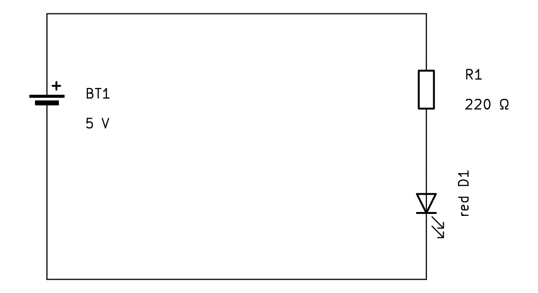
Coils and relays
The diodes unit ended with a part that absorbs "the voltage spike a coil produces when it switches off," and the next unit has you switching real loads from a Raspberry Pi. Between those two sits the coil itself. Coils are inside much of the hardware in this course: every motor, relay, and transformer is built from a coil, and coils paired with capacitors filter the signals in a radio.8 This unit covers what a coil is, why it produces a voltage spike when you switch it off, and the part built from it that you drive in Module 03: the relay.
A coil, or inductor, is a length of wire wound around a core. Current through any wire creates a small magnetic field around it. Winding the wire into a coil stacks those fields, and each turn adds to the combined field.8 The coil is the third basic component, and it is the capacitor's counterpart. A capacitor stores energy as charge and releases it when the voltage changes; an inductor stores energy as a magnetic field and releases it when the current changes. A capacitor evens out voltage, and an inductor evens out current.8 An inductor is not polarized, so either lead can go either way.8 Inductance is measured in henries (H). One henry is large, so real parts are rated in millihenries (mH) and microhenries (µH).

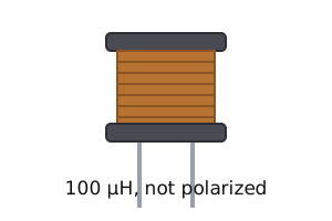
That stored field is also why switching a coil off produces a spike. While current flows, energy sits in the magnetic field. Cut the current, by opening a switch or turning a transistor off, and the collapsing field turns its energy back into current and drives a large voltage spike across the coil. The spike is called an inductive kick, and it can destroy nearby components, the part doing the switching first.8 The fix is the one from the diodes unit: a flyback diode wired backward across the coil gives the spike a harmless loop to circulate through. Flyback diodes are used with coils of every kind, including motors and relays.8 The rule: a coil you switch gets a flyback diode.
Put a coil and a switch in one package and you have the relay: an electrically operated switch. Current through the coil creates a magnetic field that pulls the contacts closed, and you can hear the click when they move. Release the coil and a spring opens them again.9 The coil side and the contact side are electrically separate circuits, and that separation is the relay's whole value: a small, low-voltage current through the coil switches a load on a completely different circuit, at a voltage or current the control side could never carry.9 The transistor in the next unit switches fast and silently on a shared circuit; the relay switches slower but keeps the two circuits fully apart. In Module 03 you drive exactly this combination, built into a relay module: a Raspberry Pi pin driving a transistor, the transistor driving a relay coil, and a flyback diode across the coil.
Transistors
You want a Raspberry Pi to switch a real load: an IR illuminator for a night camera, a relay that keys a radio, or a salvaged 12 V lamp. The Pi's pin gives 3.3 V and can source only about 16 mA.11 Wire the load straight to that pin, and you draw more current than the pin can supply and risk damaging the chip. The transistor is the part that solves this.
A transistor does not add power to a signal; it uses a small current to control a much larger one.8 A weak signal on one terminal lets a much larger current pass between the other two. The pin controls the switch, and the load current comes from a separate, larger supply, not from the pin.
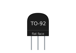
Two families take that command in different ways. A bipolar junction transistor (BJT) is controlled by a current. Its three terminals are the base, the collector, and the emitter. A small current into the base lets a much larger current flow from the collector to the emitter. The emitter carries both currents together: the large collector current and the small base current combine and exit through it, which is why it connects to ground in this switching configuration.8 The 2N2222 is a common NPN type. Small transistors like it come in the TO-92 package, a black half-cylinder with three legs in a row. The flat face tells you which leg is which, and the order varies between parts, so check the datasheet before wiring it.

Unlike a BJT, which is controlled by current, a MOSFET is controlled by a voltage. Its three terminals are the gate, the drain, and the source. A voltage on the gate above its threshold turns it on, and almost no current flows into the gate. A MOSFET also has very low on-resistance, so it wastes little power while it conducts. This is why a BJT needs a resistor to set its base current, while a MOSFET does not. It switches a load the same low-side way as the BJT: the load sits between the supply and the drain, and the source goes to ground. When a MOSFET's threshold is low enough that a 3.3 V or 5 V logic pin can turn it fully on, it is called a logic-level MOSFET, and a pin drives its gate directly, with no resistor at all. That is the first switch you build in Module 03.

Return to the BJT switch. The pin does not power the load. It only feeds the base. The load current comes from the collector supply, which can be far larger than the pin can provide. The base current does not become the collector current either. The transistor multiplies the base current by its current gain, written as the Greek letter beta.8 A 2N2222 has a gain around 100, but the gain varies widely from part to part, and the datasheet gives a range, not one number.10 Treat 100 as a planning estimate, not a guarantee.
To switch a load with a BJT, work backward from the load in three steps:
- Find the minimum base current. It must be at least the load current divided by the gain,
Ibase(min) = Iload / gain. - Pick a target above that floor, commonly two to ten times the minimum, so the transistor saturates (turns on fully) even if your part's gain runs low.
- Turn that base current into a resistor. The base-emitter junction acts as a diode and drops about 0.6 to 0.7 V once it conducts,2 so the pin voltage minus 0.7 V appears across the resistor, and
Rbase = (Vpin − 0.7) / Ibase.
A bigger base current needs a smaller resistor. This means that when the answer lands between two standard values, you round down: the smaller resistor gives more base current and keeps the transistor saturated.
Work the reference switch in the figure. A 3.3 V pin drives a 2N2222, the emitter goes to ground, and the collector carries a 200 mA load from a +5 V supply. The minimum base current is 0.2 / 100 = 2 mA. Aim a little above that for margin, say 2.6 mA. Then Rbase = (3.3 − 0.7) / 0.0026 = 2.6 / 0.0026 = 1000 ohms, and 1 kΩ is a standard part that sits right on the answer. This means the base gets 2.6 mA, above the 2 mA floor, so the transistor saturates and carries the 200 mA load with margin to spare.
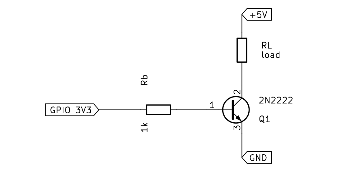
Now take a case that does not land on a standard value. The same pin and 2N2222 must switch a 250 mA load. The minimum base current is 0.25 / 100 = 2.5 mA. Aim a little above, 3 mA. Then Rbase = (3.3 − 0.7) / 0.003 ≈ 867 ohms, which is not a standard value. Round down to 820 ohms, the nearest standard value below. An 820-ohm resistor passes 2.6 / 820 ≈ 3.2 mA, slightly more base current, which keeps the switch saturated. Rounding up to 1 kΩ would push the base current toward the floor, the wrong way.
Integrated circuits
You salvage a board to reuse its chip, or you wire a chip from a schematic onto your own board. The schematic names power on one numbered pin and ground on another. The chip in your hand has no numbers on it. Miscount the pins, put power where ground belongs, and the chip is destroyed the moment you switch on. So your first job is to find pin 1 on the real part, count from it to any pin the schematic names, and place the decoupling capacitor on the right two pins.
An integrated circuit, or IC, combines the resistors, diodes, transistors, and small capacitors of a whole circuit on one chip of silicon. A small IC holds just a few components; a microcontroller or a memory holds billions.8 On a schematic, the IC is a box with a numbered, labeled pin for each connection, and the box says nothing about the part's size or shape, only its connections. The example below is the 555 timer, a common 8-pin chip.

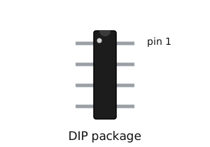
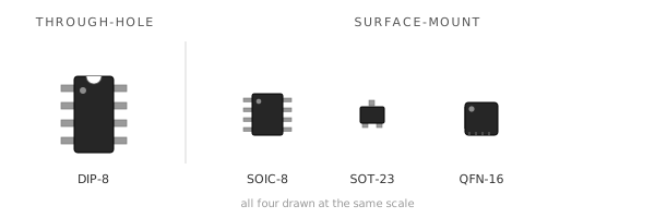
In hardware, the IC comes in a package. A through-hole IC uses the DIP package, a rectangular body with two rows of legs; a surface-mount IC uses a smaller, flatter package soldered to the board's surface. A through-hole part's legs pass through drilled holes in the board and solder on the far side.7 A surface-mount part sits flat on pads on the surface instead, and surface-mount parts dominate mass-produced boards, so they are what you find in salvage work.7 The package marks pin 1 in two ways: a notch (a half-moon cut in one short end) and a small dot pressed into the surface next to pin 1. Some salvaged chips show only one of the two marks, so each mark must be readable on its own.
The pins are numbered counterclockwise from pin 1, but counterclockwise means nothing until the chip is held in a fixed position, so use a rule that survives any rotation:
- Face the top of the body toward you, legs pointing away, notch at the top.
- Pin 1 is the pin just to the left of the notch, and the dot sits beside it.
- Always read from the top. If you flip the chip so the legs face you, left and right mirror and pin 1 moves to the other side.
- No notch, only a dot? Turn the chip so the dot is at the top-left; that pin is pin 1.
From pin 1, the next pin is the one beside it in the same row, moving away from the notch. Go down that row to its far end, cross the gap to the other row, and count back up toward the notch. On an 8-pin DIP held notch-up, that runs pin 1 at the top-left down to pin 4 at the bottom-left, across to pin 5 at the bottom-right, and up to pin 8 at the top-right. Pin 1 and pin 8 both sit beside the notch, directly across the gap from each other.
Every IC has a power pin and a ground pin among these, and most also need a decoupling capacitor, a small ceramic capacitor placed across those two pins, as close to the chip body as it fits. As the chip switches internally, it draws current in sharp bursts. The capacitor holds a small charge right at the chip and supplies those bursts locally, which keeps the supply voltage steady instead of letting it dip. It does the same job as the smoothing capacitor from the capacitor unit. A value of 0.1 µF (100 nF) is the common default, though the chip's datasheet sets the value that matters.
Work the 555 timer, an 8-pin DIP. The schematic puts ground on pin 1 and power on pin 8.
- Hold it notch-up, top toward you. Pin 1 is to the left of the notch, at the top-left. That is ground.
- Count down the left row away from the notch: pins 2, 3, 4.
- Cross the gap and count back up the right row: pins 5, 6, 7, 8. Pin 8, power, lands at the top-right, beside the notch and straight across from pin 1.
- Check: pin 1 and pin 8 both flank the notch. If your count put pin 8 at the far end, you went the wrong way.
So the decoupling capacitor goes across pin 8 and pin 1, as close to the chip as it fits.
Common circuits
A field device runs its logic at 3.3 volts, but its battery pack sits at 5 volts or more. Wire that battery straight to a 3.3 volt input and you damage the input. The device still needs to read its own battery, so it needs that 5 volts scaled down to a level the input can safely read. Two small circuits built from the parts you already know solve this and a related timing problem. The voltage divider turns an input voltage and two resistors into a fixed lower voltage a circuit can safely read. The RC circuit, a resistor and a capacitor in series, produces a fixed time delay.
Start with the divider. It provides a scaled-down copy of one voltage to another part of the circuit. Two resistors connect end to end across a voltage, with a tap wire coming off the point where they meet: the midpoint. The input splits across the two resistors, and the midpoint sits at whatever voltage is left after the top resistor drops its share. More resistance on the bottom leaves more voltage at the midpoint. More on top leaves less. As the earlier units set out, the midpoint voltage is measured against ground, the bottom of the pair, because voltage is a difference between two points.
The split comes straight from Ohm's law. The two resistors are in series, so the same current flows through both, and the voltage across each is that current times its resistance (V = I × R). The current is the same through both, so the larger resistor drops the larger voltage. This means the midpoint is set by the two resistor values alone.
The rule is Vout = Vin × R2 / (R1 + R2), where Vin is the input voltage, R1 is the top resistor, R2 is the bottom resistor, and Vout is the midpoint voltage.4 The midpoint is the input times the bottom resistor's share, and that share is the bottom resistor divided by the two added together. The output depends only on the ratio of the two resistors, so 10 kΩ over 10 kΩ and 1 kΩ over 1 kΩ both give exactly half.
Work the reference divider: Vin is 5 volts, R1 is 10 kΩ on top, R2 is 10 kΩ on the bottom. Substitute into the rule: Vout = 5 × 10 / (10 + 10) = 5 × 0.5 = 2.5 V. The two resistors are equal, so the input splits evenly and the midpoint lands at half of 5 V. This means an equal pair always halves the input.
The opening problem runs this in reverse: you know the input and the voltage you want, and you pick the resistors. To scale a 5 V pack down to 3.3 V, you need the bottom share to equal 3.3 / 5 = 0.66. Pick the top resistor first, say R1 = 10 kΩ, then size R2 so its share is 0.66: R2 = 20 kΩ gives 20 / (10 + 20) ≈ 0.667, so the midpoint reads about 5 × 0.667 ≈ 3.3 V. The device can now read its own battery through an input that only tolerates 3.3 V. This is the divider's most common job on a circuit board.
The tool below builds the divider live. Drag the input and the two resistors, and the midpoint follows the same fraction every time: the bottom resistor divided by the total.
Interactive The voltage divider Drag the input and the two resistors, and watch the midpoint voltage follow their ratio. Open it full screen →The second circuit is the RC, a resistor and capacitor wired in series. Its job is to produce a fixed delay with no processor: the wait before a reset releases, the debounce on a noisy button, the rate of a blinking light. One point confuses beginners here. Apply a voltage across the pair and the capacitor's voltage does not jump up to meet it. The capacitor charges through the resistor, and its voltage rises on a curve, fast at first and slowing as it nears the supply. The reason is Ohm's law again. At the start the capacitor is empty, so the full supply sits across the resistor and a large current flows. As the capacitor fills, less voltage is left across the resistor, the current drops, and charging slows.
How long this takes is set by the resistor and the capacitor together. One time constant is the resistance times the capacitance, written with the Greek letter tau: τ = R × C, with R in ohms, C in farads, and tau in seconds. After one time constant, the capacitor reaches about 63% of the supply voltage.5 After five it is about 99% of the way there, which counts as full. Double either part and you double the time.
Work the reference RC: R is 10 kΩ (10,000 ohms) and C is 100 µF (0.000100 farads). Then τ = R × C = 10,000 × 0.000100 = 1 second. This means the capacitor should read about 63% of the supply at one second. Simulation gives 3.16 V at one second (63% of 5 V) and 4.97 V at five seconds, essentially full.
The tool below sets the resistor and the capacitor, then charges the capacitor on a trigger. The output crosses its threshold at 63% of the supply, one time constant in.
Interactive The RC time constant Change R and C, and watch the charging curve and the time constant move with them. Open it full screen →A third pattern built from a single resistor solves a different problem: a digital input pin connected to nothing. An unconnected input does not read a clean 0 or 1; it floats, picking up stray voltage and reading unpredictably. A pull resistor ties that pin to a known level, so it holds steady until something actively drives it the other way.
A pull-up resistor connects the pin to the positive supply: the pin reads high at rest, and a button or output pulls it low when it acts. A pull-down connects the pin to ground instead: the pin reads low at rest, and the button pulls it high. The difference is the level a disconnected pin rests at: with a pull-up it goes high, with a pull-down it goes low.8 The resistor is large enough to waste little current but small enough to hold the line firmly, commonly 1 kΩ to 10 kΩ. This is the pattern behind buttons, enable pins, and the two lines of an I²C bus. You wire it in the next module.
Reading a schematic
Describing a circuit in words is slow, and tracing its wires in a photograph is hard. A schematic solves both problems. It draws the symbols from the earlier units and joins them with lines that show how the parts connect. To read one, you recognize each part from its symbol and follow the lines to see what connects to what.
What a schematic records is the connections, not the shape of the wires. Two circuits drawn differently are the same circuit when the same parts connect the same way. A line can bend or run long or short without changing anything. Read a schematic for what touches what, and ignore how the drawing is arranged.
Each part on a schematic has a name made of one or two letters and a number. The letter gives the type: R is a resistor, C a capacitor, D a diode, Q a transistor, U an integrated circuit, SW a switch (S in some schematics).6 The number makes the name unique when a circuit has more than one of a kind, so three resistors are R1, R2, and R3. The value sits beside the name: 1k for a 1 kΩ resistor, 100 µF for a capacitor. Name and value together pin down exactly which part goes there.
A line is a wire. It is an electrical connection between the points it touches. Where one wire branches off another, a dot marks the join, and the wires meeting at that dot are one connected point. Two lines that cross with no dot are not connected. They only pass over each other.6
Wires do not always run all the way across the page. A connection point can be given a name instead, and every point with that same name is connected as if a wire ran between them.6 This keeps a crowded schematic readable. You saw it on the voltage divider, where Vin, Vout, and GND named the connection points instead of long wires.
Schematics follow a layout convention so they read the same way every time. The supply sits toward the top, ground toward the bottom, and a signal runs left to right, from its input on the left to its output on the right. Every figure in this module is drawn that way. Once you expect it, you can find the power and the ground of an unfamiliar circuit at a glance.
The tool below builds these skills in order: name each symbol by its type letter, decode a part's name and value, tell a junction from a crossover, and read the power, ground, and signal of a circuit from where they sit. The nets-and-junctions tab shows a filled dot where wires join at one node, and a crossover with no dot that leaves two wires unconnected.
Interactive Reading a schematic Practice four skills in order: recognize the symbol, decode the name and value, follow the nets, and use the layout. Open it full screen →The last tab puts every skill on one circuit: the transistor-driven LED node, the switch that runs a load from a single Pi pin. A pin named GPIO 3V3 drives the base of a 2N2222 through a 1 kΩ resistor; the transistor switches a red LED and its 220 Ω resistor from the +5V rail; a 100 nF capacitor decouples the supply. You name each part by its symbol and designator, follow +5V and GND as named nets, and trace the path from the pin on the left to the LED on the supply side. A simulation of this exact circuit confirms the reading: about 2.6 mA into the base saturates the transistor, its collector sits near 0.04 V, and the 220 Ω resistor holds the LED current at about 14 mA, close to the 13.6 mA the diodes unit estimated by hand.
The multimeter
A salvaged or hand-built circuit fails, and you do not know why. You build the LED loop from the diodes unit, or you pull a board from a dead device, and nothing lights. The multimeter locates the fault; without it you are guessing. You set the meter and connect it correctly to take the five measurements you need: voltage, resistance, continuity, current, and a direct diode or LED check. The meter you learn to set here is the same meter you reach for to test a salvaged part, troubleshoot a soldered joint, or check an RF feedline in every module after this one.
A common mistake is expecting the meter to report a number no matter how the probes touch the circuit. It does not work that way: the meter becomes part of the circuit while it measures, so the way you connect it determines whether the reading is true. Voltage is always the difference between two points, so a voltage reading needs both probes, one on each of the two points you are comparing. Current is the whole flow along a path, so to read it the meter has to sit inside that path and let the current pass through it. Every measurement is three choices, and getting any one of them wrong gives you a useless reading or damages the meter:
- What to measure: the rotary dial in the middle.
- Where the leads plug in: the jacks at the bottom.
- How you connect: probes across a part or breaking into the loop, and the power on or off.
The dial selects what you measure. For the DC circuits in this series, you use five settings: DC voltage, marked V with a straight or dashed line; resistance, marked Ω; continuity, marked with a sound-wave symbol; current, marked A; and diode test, marked with a small triangle and bar.3 The jacks select the path the leads take. The COM jack is the common return, and it always holds the black lead. The VΩmA jack (marked INPUT on some meters) holds the red lead for voltage, resistance, continuity, and small currents. A separate A jack holds the red lead for larger currents.3 The current jacks are fused because measuring current puts the meter directly in the circuit's path, where a wrong connection can drive a large current through it. The fuse fails first and protects the meter.
One more setting sits outside the DC work, but you use it in the field exercise: AC voltage, marked V with a wavy line (~) instead of a straight or dashed one. A wall outlet and the mains behind it carry alternating current, which the DC-volts setting reads wrong, so a live outlet is measured on AC volts. This is the only reading in the module taken on mains voltage, so treat it with care: set the dial to AC volts first, hold the probes by their insulated handles only, and never touch the metal tips once the circuit is live. The meter must be marked CAT II or better on its face. If yours is not, or you are unsure, skip the outlet reading. The field exercise works without it.
Two rules then decide how you wire each measurement. The connection rule: you read voltage and continuity with the probes touching across the part, which is a parallel connection, and you read current with the meter in series, breaking the loop so the current flows through it.3 The power rule: the power stays on for voltage and for current, and it goes off for resistance and for continuity, because a resistance reading on a live circuit is wrong and can damage the meter.3 One more choice exists only on a manual meter. It prints numbered ranges under each setting, such as 2 V, 20 V, and 200 V, and you turn the dial to the range just above the value you expect. A range set too low shows a lone 1 or OL, which means the reading is over the range, and you move the dial up one step.3 An auto-ranging meter picks the range itself.
| To measure | Dial | Power | How you connect |
|---|---|---|---|
| Voltage | DC volts | On | Both probes across the part, in parallel |
| Resistance | Ω | Off | Across the part, with one end lifted out of the circuit |
| Continuity | Continuity | Off | Across two points; it beeps if connected |
| Current | A | On | In series, breaking the loop so current flows through the meter |
| Diode/LED check | Diode test | Off | Across the part, anode to red probe; reads its forward voltage directly |
Voltage is the measurement you reach for most, so work it first on the LED loop you followed all module: a 5 V supply, a 220 Ω resistor, and a red LED in one loop. The diodes unit found that the resistor drops 3.0 V and the red LED drops about 2.0 V. Confirm those two numbers with the meter, in order:
- Set the dial to DC volts.
- Place the leads: black in
COM, red in theVΩmAjack. - Leave the power on. A voltage reading is taken on a live circuit.
- Touch the probes across one part at a time. Red on one end of the resistor, black on the other: the display reads about 3.0 V, the difference between those two points. Move both probes onto the LED and it reads about 2.0 V.
- Pick the range on a manual meter: you expect a few volts, so the 20 V range sits just above the value.
The two readings add to 5.0 V, the supply. That sum is your sanity check that the meter and the loop agree.
Voltage confuses beginners in one specific way. People speak of the voltage at a single point, yet voltage is always the difference between two points. Both are true at once. When someone names the voltage at a single point, they mean its voltage relative to a fixed reference node called ground. To read it, you hold the black probe on that ground node and touch the red probe to the point. The single-point number is shorthand for a two-point difference, with the second point understood to be ground.
Current is the measurement people get wrong, so work it next on the same loop, where the diodes unit calculated 13.6 mA. The mistake to unlearn is reaching to touch the probes across a part, the way you did for voltage. Current is measured in series: you open the loop at one point and put the meter in the gap.
- Break the loop at one point, leaving two freed ends where it used to close. The meter takes the place of that missing link: red probe to the resistor's freed end, black probe to the LED's freed end, so the current that used to cross that point now runs in through the red probe, through the meter, and out the black probe.
- Set the dial to A.
- Place the leads: black in
COM, red in theVΩmAjack, because 13.6 mA is well under that jack's limit. - Pick the range on a manual meter: the 20 mA range reads to about 19.99 mA at full scale, so 13.6 mA fits inside it.
- With the probes bridging the gap, power the circuit. The display reads about 13.6 mA, matching your calculation. When you finish, turn the dial back to volts.
A fifth setting checks the LED directly, with no circuit math needed. Diode test pushes a small known current through the part in the forward direction and shows the voltage it drops. That is the same forward voltage you reached by subtraction in the voltage step.
- Turn the dial to diode test, power off. The meter supplies its own test current.
- Touch red to the anode, black to the cathode. A working LED reads its forward voltage, about 2.0 V for this one.
- Reverse the probes. It reads OL (open), because current cannot flow backward through it.
A failure shows in the pattern: an LED failed open reads OL in both directions; one failed shorted reads a low voltage in both directions. This is the test you reach for on a part with no schematic behind it: a diode or LED pulled from a salvaged board, with no circuit values to subtract, tested directly to see whether it still works.
The first tool is the meter itself. Walk through its parts, then see what each dial setting does.
Interactive The multimeter Identify the parts of a digital multimeter and what each dial setting measures. Open it full screen →The second tool is a bench trainer. For each of five common measurements (volts, resistance, continuity, an LED, and current), turn the dial to the right setting and read what the meter shows. Each one confirms when the dial is right.
Interactive Use the meter Take five measurements, each with one dial setting and one reading off the display. Open it full screen →Field exercise
Task: Verify the condition of a battery, a cable, a fuse, and an AC outlet using a multimeter.
Condition: Given a multimeter and access to a battery, a cable, a fuse, and an AC outlet in your home, workplace, or vehicle. The outlet reading is optional and takes a meter marked CAT II or better; skip it otherwise.
Standard: Each reading taken and logged with the correct dial setting, correct probe placement, and a pass/fail call against the expected range on the worksheet. The product of this exercise is the completed field exercise worksheet, dated and carrying every reading with its meter setting and its pass or fail call. The sheet states what each item measured on this date, and the next test of the same battery, cable, or fuse is compared against it.
Download the field exercise worksheet (PDF)
The multimeter is the instrument this module adds to the kit. Before a salvaged cell, a found cable, or an unknown outlet feeds any project, the meter reads it first: voltage before connection, continuity before power, current only in series. The reading habit from the field exercise is the same one used at every bench in the series.
Module test
Task: Complete the Module 02 test.
Condition: Given ten questions covering units one through thirteen, without reference to the module units or notes.
Standard: Answer at least eight of ten questions correctly. For each question missed, reread the unit named in the feedback and retake the test until the standard is met.
Glossary
- ampere (amp, A)
- The unit of current. Small circuits use milliamps (mA, thousandths) and microamps (µA, millionths).
- anode
- The positive terminal of a diode or LED. Current enters at the anode and leaves at the cathode.
- capacitance
- A capacitor's capacity to store charge, measured in farads (F).
- capacitor
- A component that stores electric charge. Common types are ceramic (small values, non-polarized) and electrolytic (large values, polarized).
- cathode
- The negative terminal of a diode or LED, marked by a band on a diode and a flat on an LED.
- circuit
- A complete loop that carries current from a source, through components, and back. Current flows only while the loop is unbroken.
- coil (inductor)
- A length of wire wound around a core. It stores energy as a magnetic field and releases it when the current changes. Not polarized. Inductance is measured in henries (H).
- conductor
- A material that carries current easily, with very low resistance, such as the copper in a wire.
- current
- The flow of electric charge through a conductor, measured in amperes.
- decoupling capacitor
- A small ceramic capacitor placed next to an IC's power and ground pins to steady the supply as the chip switches.
- DIP
- Dual in-line package. A through-hole IC package: a rectangular body with two rows of legs.
- diode
- A component that conducts current in one direction only, from anode to cathode.
- electrolytic capacitor
- A capacitor of large value that is polarized and must be connected the right way round. A stripe marks its negative lead.
- farad (F)
- The unit of capacitance. One farad is large, so real parts are rated in microfarads (µF), nanofarads (nF), and picofarads (pF).
- flyback diode
- A diode wired backward across a coil to give the inductive kick a harmless loop to circulate through when the coil switches off. Also called a freewheeling diode.
- forward voltage
- The voltage a diode drops once it conducts: about 0.7 V for a silicon diode, 0.15 to 0.45 V for a Schottky, and about 1.8 to 3.3 V for an LED depending on color.
- gate
- The control terminal of a MOSFET. A voltage on the gate switches the MOSFET on or off, and almost no current flows into it.
- henry (H)
- The unit of inductance. One henry is large, so real parts are rated in millihenries (mH) and microhenries (µH).
- inductive kick
- The voltage spike a coil produces when its current is cut and the magnetic field collapses. A flyback diode absorbs it.
- integrated circuit (IC)
- A chip that packs many components onto one piece of silicon, from a few transistors to billions.
- insulator
- A material that blocks current, with very high resistance, such as the plastic insulation around a wire.
- LED
- Light-emitting diode. A diode that gives off light when it conducts. It needs a series resistor to limit the current.
- MOSFET
- A transistor switched by a voltage on its gate, with very low on-resistance. Its terminals are the gate, drain, and source.
- ohm (Ω)
- The unit of resistance.
- Ohm's law
- The current through a resistor equals the voltage across it divided by its resistance:
I = V / R. - parallel circuit
- A circuit with more than one path. The current splits between the paths, and the full source voltage appears across each path.
- pin 1
- The reference pin of an IC, marked by a dot or a notch. The pins are numbered counterclockwise from pin 1.
- polarized
- Having a positive and a negative terminal that must be connected the right way round, as in an electrolytic capacitor or a diode.
- power
- The rate at which a component converts electrical energy, measured in watts. In a resistor it all becomes heat. Power is voltage times current:
P = V × I. - pull-up / pull-down resistor
- A resistor that ties a digital input to a known level so it does not float: a pull-up holds the pin high at rest, a pull-down holds it low. Commonly 1 kΩ to 10 kΩ.
- relay
- An electrically operated switch: current through its coil pulls the contacts closed. The coil circuit and the contact circuit are electrically separate, so a small control current switches a larger, isolated load.
- resistance
- A material's opposition to the flow of current, measured in ohms (Ω).
- resistor
- A component with a specific, known resistance, used to set how much current flows in part of a circuit.
- schematic
- A drawing of a circuit that uses a standard symbol for each component instead of a picture of it.
- Schottky diode
- A diode with a low forward voltage, about 0.15 to 0.45 V, that switches faster than a standard silicon diode.
- series circuit
- A circuit with a single path. The same current flows through every component in turn.
- short circuit
- A path of almost no resistance straight across a source. The current spikes until something fails.
- surface-mount
- A part soldered directly to the surface of a board, smaller and flatter than a through-hole part.
- switch
- A component that opens or closes a circuit, breaking or completing the loop.
- TO-92
- A small black half-cylinder package with three legs, used by transistors such as the 2N2222. The flat face is the pinout reference.
- tolerance
- How far a resistor's true value may differ from its marked value. Gold is ±5 percent, silver is ±10 percent.
- transistor
- A component that uses a small current or voltage to control a much larger current, used as a switch or an amplifier. The two families are the bipolar transistor and the MOSFET.
- voltage
- The difference in electrical potential between two points, measured in volts. It drives current through a circuit.
- watt (W)
- The unit of power.
Sources
- SparkFun: Diodes. One-way conduction from anode to cathode; the forward-voltage drop; the cathode band; LEDs and the series current-limiting resistor.
- SparkFun: Transistors. The NPN bipolar transistor: base, collector, and emitter; the base-emitter junction turns on at a diode-like drop of roughly 0.6 to 0.7 V; the current gain (beta) multiplies the base current.
- SparkFun: How to Use a Multimeter. Voltage measured in parallel; current in series through the fused jack; resistance and continuity measured unpowered.
- SparkFun: Voltage Dividers. Two series resistors split a voltage;
Vout = Vin × R2 / (R1 + R2); the output is set by the ratio of the resistors, and equal resistors give half the input. - RC time constant. The time constant
τ = R × C; a capacitor charges through the resistor to about 63.2% of the applied voltage in one time constant. - SparkFun: How to Read a Schematic. Reference designators (R, C, D, Q, U, S, each numbered uniquely) and values; junctions, where a dot marks connected wires and a crossing without a dot does not; named nets; and the left-to-right layout convention.
- Surface-mount technology. Surface-mount parts solder directly onto pads on the board surface, are smaller, allow higher density on both sides, and dominate machine assembly; through-hole leads pass through drilled holes, give a stronger mechanical bond, and are easier to hand-solder and prototype.
- Jonathan Bartlett, Electronics for Beginners: A Practical Introduction to Schematics, Circuits, and Microcontrollers, Apress, 2020. Plain-language treatment of charge and current, voltage and resistance, Ohm's law, power, series and parallel circuits, diodes, resistor patterns (current-limiting, voltage divider, pull-up and pull-down), capacitors and RC time constants, the capacitor three-digit marking code, inductors and the inductive kick, the 555 oscillator, integrated circuits and pin numbering, logic ICs, the BJT and MOSFET as switches, the breadboard, and the multimeter.
- Relay. An electrically operated switch: current through the coil moves the contacts, and the control circuit is electrically separate from the switched circuit, so a low-power signal switches a higher-power or isolated load.
- ON Semiconductor, 2N2222A datasheet, Rev. 2, 2013. DC current gain (hFE): minimum 100 and maximum 300 at 150 mA collector current, with limits from 30 to 325 across test conditions.
- Raspberry Pi documentation: GPIO pad controls. “All the electronics of the pads are designed for 16mA. This is a safe value under which you will not damage the device.”