On this page
Draw it, then prototype it
Every circuit in this module is built the same way: drawn in KiCad first, proven on a breadboard with the multimeter second, and wired to the Raspberry Pi last. This unit covers the drawing and the prototype; the two builds that follow use both.
Draw it. Every build starts as a KiCad schematic, drawn on the laptop you hardened in Module 00, with the same symbols you learned to read in Module 02. The drawing is itself the first test: KiCad's electrical rules check automatically detects incorrect and missing connections, such as an unconnected pin or a power input that no output pin drives, before you handle a single part.5 KiCad can also lay out a printed circuit board for fabrication, but that is beyond this course. Here, you build from the schematic.
Interactive Draw it in KiCad Follow Build 1's schematic drawn in KiCad: placing parts, wiring them, running the electrical rules check. Open it full screen →Prototype it. A solderless breadboard lets you assemble a circuit with no soldering at all, so you can try your designs before committing them to solder.1 Beneath its holes sit short metal rows called terminal strips: any two wires or leads plugged into the same strip are electrically connected.4 A gap called the bridge runs down the middle and splits the board in two, so a chip can straddle it with each leg landing on its own terminal strip.4 Along each edge runs a pair of power rails, one marked with a red line and one with a blue line; the rails carry the supply the length of the board.4
To build the circuit on a breadboard, place the real parts so their connections match the schematic, node for node. Give each leg of a part its own strip, because putting both legs into one strip shorts the part out.4 Then prove the build with the multimeter in two passes:
- Before power, continuity. Set your multimeter to continuity mode. Touch the probes to any two points the schematic shows as connected, and the meter should beep. Touch two points from different parts of the circuit that the schematic does not connect, and the meter should stay silent.
- Under power, voltage. Set your multimeter to DC volts. Put the black probe on ground, then touch the red probe to each point the schematic labels with a voltage, and check that the meter reads that value.
Make it permanent. A breadboard is temporary, since its wires tend to fall out after a while.1 Once a circuit works, transfer it to perfboard or stripboard. Both are perforated boards you cut to size and solder the parts onto: stripboard carries conductive strips underneath, while perfboard has an isolated pad at each hole.1 Positions do not need to match the schematic; only the connections do.
Batteries and power
The basic unit of a battery is the cell; a battery, strictly speaking, is "a group of two or more connected voltaic cells,"6 though in everyday use the word covers both. A cell you use once and throw away is a primary cell, and one you can recharge is a secondary cell.6
A cell has three ratings that matter here: voltage, capacity, and C-rate. Voltage is how hard the cell pushes current; capacity, in milliamp-hours, is how much charge the cell holds.
A 3000 mAh cell can supply 3000 mA, or equivalently 3 A, for one hour.1 Divide the capacity by the current your circuit draws to estimate the runtime: a circuit drawing only 30 mA should run for about 100 hours on that same cell (3000/30).1 Treat that as an estimate, not a guarantee: the harder you draw, the less of the rated capacity you actually get, so build in margin. Real cells typically deliver only about 25 percent of their theoretical capacity (the capacity computed from the raw materials alone); the mAh rating printed on the label already accounts for this and is the number you plan with.7
The third rating, the C-rate, sets the maximum current you may draw. One C means draining the whole capacity in one hour, so a cell rated at 2 Ah with a maximum continuous discharge of 4 A has a C-rate of 2.8 Drawing past that rating overheats the cell, hot enough in some cases to catch fire.1 Use the calculator below to run the arithmetic.
Interactive Battery runtime Set the capacity and the current draw, read the runtime, and see how much extra current a boost converter adds. Open it full screen →The voltage printed on the label is not what you get under load; the reason is internal resistance. A multimeter across a fresh cell reads its full voltage, but the moment current flows, that resistance drops the terminal voltage the cell delivers.6
A fresh 1.5-volt AA settles near 1.3 V under load and still delivers useful power down to about 1 V, so a four-cell pack can sit anywhere between 4 and 6 volts.1 A 9-volt battery delivers between 7 and 10 volts depending on its chemistry and wear.4 Lithium cells sag under load too, and on an RC LiPo you watch that sag closely: the cell should never drop below 3.0 V while in use.8
Cells combine two ways. Wired in series, positive to negative, the voltages add while the current stays the same, so four 1.5-volt cells in series give a total of 6 volts.6 Capacity does not add in series: four 1.5-volt, 2000 mAh cells in series still hold 2000 mAh, just at 6 volts instead of 1.5.1 Parallel is the reverse: the voltage stays the same and the capacities add.6 Parallel comes with one hard rule: match the cells' voltages before you join them, or the fuller cell dumps a large amount of energy at once into the less charged one, which can cause a fire.8
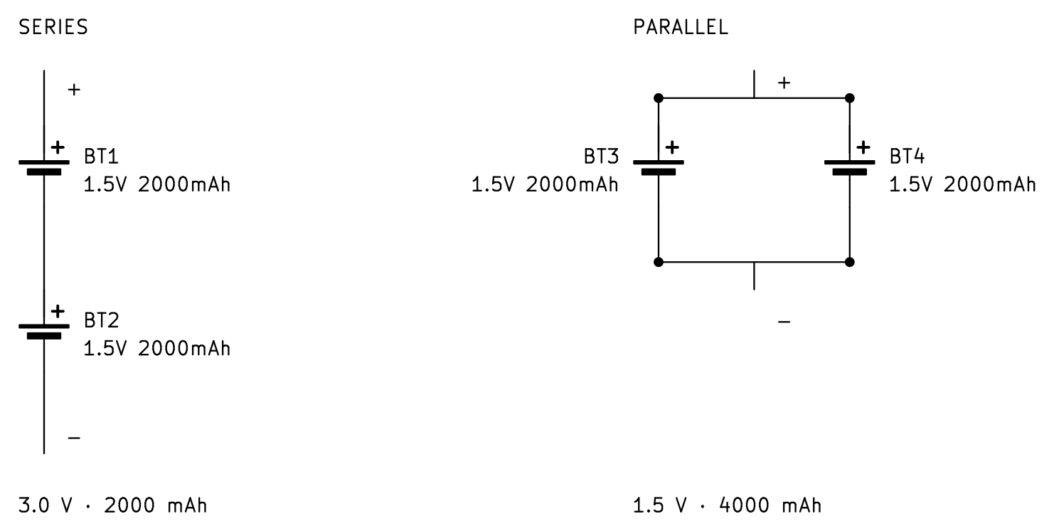
Each chemistry is a trade-off. Alkaline cells are the cheapest option: they hold 1.5 volts and keep their charge for years, losing only about 4 percent of it annually, but as primary cells, they must be discarded once dead.7 NiMH rechargeables hold about 75 watt-hours per kilogram, less than an alkaline cell but rechargeable hundreds of times, though they self-discharge faster in storage as temperature and charge level rise.7 Lead-acid stores about 30 to 40 Wh/kg, the least of the four, and is heavy for the energy it holds. It is also the most robust of the four technologies, with the least chance of fire or explosion.1 7 13 Lithium-ion, including its soft-pouch form, stores far more than any of the others, about 150 Wh/kg at 3.6 volts nominal and 4.2 volts full, and survives more than a thousand charge cycles.7
That density is why a lithium cell powers a Raspberry Pi in the field. The cell does not feed the board directly: a Pi requires a steady 5 volts, and a sensor often requires 3.3, so the cell feeds a regulator or a boost converter.
Correct one term before you shop for cells: what the market sells as "LiPo" is not a separate chemistry, but a lithium-ion cell packed in a soft pouch. A true lithium-polymer cell, one with a solid polymer electrolyte, never became a commercial product.8 The high-discharge "RC LiPo" sold for hobby aircraft is a specific cobalt chemistry, and Toll states plainly: “RC lipo batteries are the dangerous ones,” and they “can be safe, but they are also incredibly volatile when used improperly.”8
Charging a lithium cell takes more than applying voltage. A proper charger runs in two phases, first pushing a steady current until the cell reaches its 4.2 V limit, then holding that voltage while the current tapers off.8 7 In practice that means charging at 4.2 V with the current capped, usually around 0.5 A, and charging slowly, since most lithium cells should not be charged faster than 0.5 C.1 8 The TP4056 board used in the field exercise is a single-cell charger that runs this sequence automatically.
Set up the controller
Both builds in this module use one controller, the Pi Zero 2 W. It is smaller than the Pi 5 that runs your Module 01 node, and it carries the same 40-pin header. In this unit you bring the board online and register it on your VPN. Before you wire anything to the header, study the board in the explorer below.
Interactive Pi Zero 2 W Click any marker on the Pi Zero 2 W to read that component and the job it does in the build. Open it full screen →The header comes fitted. This module specifies the Zero 2 WH, the same board with the 40-pin header already on it, so every connection here is a jumper onto a pin. Later modules stack field hardware onto this header; keep it unobstructed.
Set up the board first. The Zero 2 W arrives blank, and you prepare it exactly the way you prepared the Module 01 node: from the hardened laptop, with no monitor ever attached.
- In Raspberry Pi Imager, choose Raspberry Pi OS Lite (64-bit).2
- In the Imager's settings, give the board its own hostname, enable SSH with the same public key your laptop already uses for the node, and enter your Wi-Fi credentials for the 2.4 GHz network; the Zero 2 W has a 2.4 GHz radio only.2 Name the board
dolos. Dolos is the remotely deployed device this series builds toward; this board is its controller, and it carries the hostname for the rest of the series. - Boot it and reach it from the laptop:
laptop $ ssh user@dolos.localThe board is now a node on the LAN you built in Module 01, and every command in the rest of this module is typed into that SSH session. Two tools do the GPIO work on current Raspberry Pi OS: pinctrl, which ships with the OS and drives a pin from the shell, and gpiozero, the Python library.2 Both count pins by GPIO number, not by position on the header: GPIO18 is physical pin 12. The wiring figures label physical pins and give the GPIO number beside each. OS Lite may not include the library, so install it once:
dolos $ sudo apt update && sudo apt install -y python3-gpiozeroThen register it on your VPN. Module 01 set up a Headscale control server on your VPS and a private network your devices share. On your LAN, dolos.local answers; off the LAN, that name does not resolve. Registration gives the board a private address that works on any network, and it uses the same non-interactive flow as the Module 01 node: the board has no browser, so a pre-auth key from the control server registers it in one command.11 Create the key on the control server (--user 1 is the user you created in Module 01; headscale users list shows it), install the client on the board,12 then register:
vps $ headscale preauthkeys create --user 1 --expiration 1h # prints a one-time key
dolos $ curl -fsSL https://tailscale.com/install.sh | shdolos $ sudo tailscale up --login-server https://headscale.your-domain --authkey YOUR_KEYConfirm from the control server: headscale nodes list shows the board with its 100.64 address. From now on, SSH reaches the board at that address from any registered device, on any network. One caution: those private addresses get reused as nodes come and go, so SSH can refuse a reused address with a host-key warning. Confirm you have reached the right board, clear the stale key with ssh-keygen -R followed by the address, and reconnect.
Build: the isolated switch
This build is the payload switch: a logic pin switching a load that shares no wires with the Pi. A GPIO pin outputs 3.3 volts and should source no more than about 16 mA,2 while a payload runs on its own supply, at voltages and currents beyond the pin's ratings. A relay is essentially an electromagnet that closes switch contacts; because the coil and the contacts are electrically isolated from each other, relays are well suited to switching separately powered devices on and off.1 The contacts give full isolation: the switched circuit shares nothing with the Pi, not even ground.
A Pi cannot drive a relay coil directly: the SRD-05VDC-SL-C's coil pulls about 72 mA at 5 volts,3 several times what the pin can safely give. So a small transistor does the driving. A standard relay driver combines a 2N3904 transistor (electrically similar to Module 02's 2N2222), a 1 kΩ base resistor, a 1N4001 diode, and a 5-volt relay.1 Module 02 covered the transistor and the diode as symbols and packages. The 1-channel relay board used here (high/low level trigger), carrying a SONGLE SRD-05VDC-SL-C relay, already has those parts built in.
The load here is deliberately small: a red LED with a 470 Ω series resistor, on a 9 volt battery of its own. The LED drops about 2 volts, so the resistor sets the branch current near (9 − 2)/470, about 15 mA.3 The LED is a stand-in: what matters is that the LED's circuit and the Pi's circuit are electrically separate, and the relay's contacts are the only connection between them.
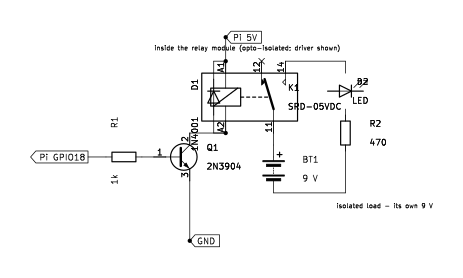
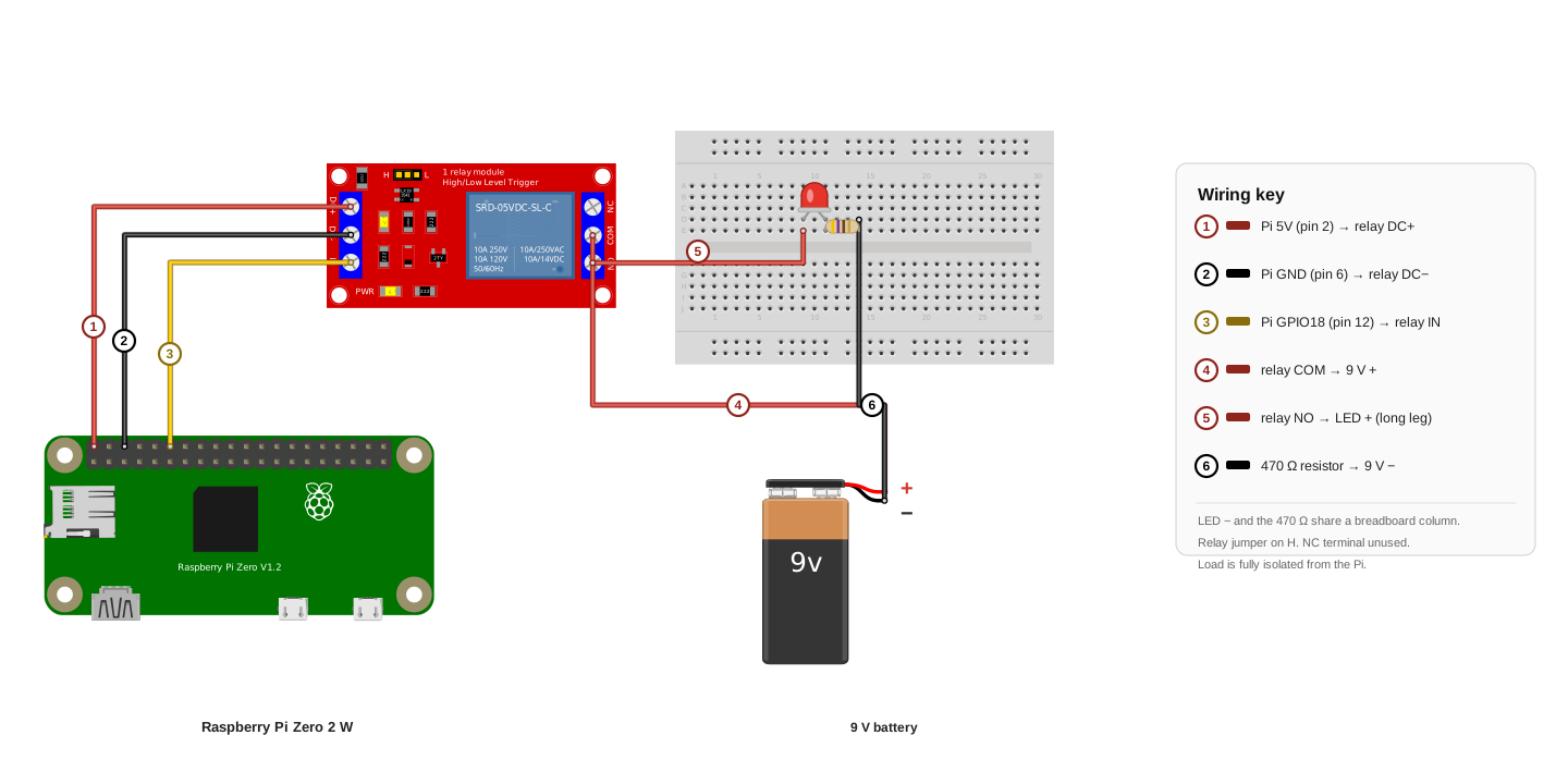
Wiring key
- Pi 5 V (pin 2) to relay DC+
- Pi GND (pin 6) to relay DC−
- Pi GPIO18 (pin 12) to relay IN
- Relay COM to 9 V +
- Relay NO to the LED’s anode, the long leg
- 470 Ω resistor to 9 V −
The LED’s cathode and the 470 Ω resistor share a breadboard column. The relay’s trigger jumper is on H, and the NC terminal stays empty. The load is fully isolated from the Pi.
Build it in this order.
- Set the module's trigger jumper to H (high-level trigger).
- Run the control side: 5 volts (pin 2) to DC+, ground (pin 6) to DC−, GPIO18 (pin 12) to IN.
- Seat the LED and resistor on the breadboard: anode (the long leg) in its own column, cathode sharing a column with one leg of the resistor.
- Run COM to the 9 volt battery's positive lead and NO to the LED's anode column; the resistor's far leg returns to the battery's negative lead.
- Connect the 9 volt block last. NC stays empty.
Prove it. Drive GPIO18 high and low from the SSH session:
dolos $ pinctrl set 18 op dh # output, drive high: relay closes
dolos $ pinctrl set 18 op dl # drive low: relay releases
The test is the sound: if the build is working, the relay module clicks on and off,1 and the LED lights on its own battery. Then make two meter checks. Check continuity between the Pi's ground and the load battery's negative lead: the meter reads OL and never beeps, because the two circuits share nothing. Measure current with the meter in series with the LED: it reads about 15 mA, matching the calculation above.
If it fails. If the pin is high and nothing clicks, check the trigger jumper's setting, and confirm with your meter that 5 volts is present between the module's DC+ and DC−. If the relay clicks but the LED stays dark, check the LED's polarity (the long leg belongs on the NO side) and the load battery's own voltage.
Field exercise: the tamper tripwire
The field exercise combines the circuits this module proved into one self-powered device: a cached node that sounds an alarm when it is handled. The chain is sense, decide, actuate: an accelerometer detects the movement, the Pi checks whether it crossed a threshold, and the relay from the last build sounds a buzzer on its own isolated supply.
The sensor. The ADXL345 is a three-axis accelerometer on a breakout board. It runs from the Pi's 3.3 volt rail (its supply range is 2.0 to 3.6 volts) and connects over I2C; with its SDO pin tied low, it answers at address 0x53.10 At full resolution it reports acceleration in steps of about 3.9 mg, so a device sitting still reads gravity as a steady vector, and any handling shows up as a change against that baseline.10
The bus. I2C is a two-wire bus: SDA carries the data and SCL the clock, and one pair of pins serves every device on it, each device answering at its own fixed address. On the Pi's header the pair is GPIO2 (pin 3) and GPIO3 (pin 5), and those two pins carry fixed pull-up resistors, so the bus needs nothing added.2 Enable the bus once in raspi-config (Interface Options, I2C),2 install the tools, and the sensor should answer:
dolos $ sudo raspi-config # Interface Options → I2C → enable
dolos $ sudo apt install -y python3-smbus i2c-toolsdolos $ i2cdetect -y 1 # a 53 in the grid is the ADXL345
Power it from a pack, not the wall. A cached device runs on its own power, and the pack is built from parts on hand: a 3.7 volt LiPo, a TP4056 charger (the two-phase charger introduced in Unit 02), and an SX1308 boost module set to 5 volts. Wire the cell's positive lead through the slide switch to the TP4056's B+ pad, and the negative lead to B−. Feed the SX1308's input from the same pads. Before connecting the pack to the Pi, power the chain and set the SX1308's trimmer (a small screw-adjust potentiometer) until the output reads 5.0 volts on your meter. The module adjusts across a wide range, so it is set first and loaded second.3 One rating matters: a Pi Zero 2 W under load can pull more than 0.5 A from a 3.7 volt cell, so the slide switch on the cell line must be rated above 0.5 A.
Runtime follows Unit 02's capacity rule with two corrections: the boost loses some energy as heat, and the Pi's draw varies. The 320 mAh cell at 3.7 volts holds about 1.2 watt-hours, and a Pi Zero 2 W draws about 120 mA at 5 volts sitting idle, about 0.6 watts.9 The capacity rule gives 1.2 over 0.6, about two hours; the boost converter loses some energy as heat and the radio draws brief peaks, so plan on less than that.
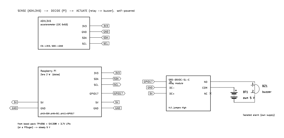
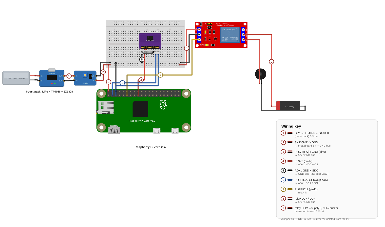
Wiring key
- LiPo to TP4056 to SX1308: the boost converter’s 5 V output
- SX1308 5 V and GND to the breadboard’s 5 V and GND bus
- Pi 5V (pin 2) and GND (pin 6) to the 5 V and GND bus
- Pi 3V3 (pin 17) to the ADXL345’s VCC and CS
- ADXL345 GND and SDO to the GND bus, which sets I2C address 0x53
- Pi GPIO2 and GPIO3 (pins 3 and 5) to the ADXL345’s SDA and SCL
- Pi GPIO17 (pin 11) to relay IN
- Relay DC+ and DC− to the 5 V and GND bus
- Relay COM to the buzzer’s supply positive, NO to the buzzer
The buzzer runs on its own 5 V rail. The relay’s trigger jumper is on H, the NC terminal stays empty, and the buzzer’s rail is isolated from the Pi.
Wire it in this order.
- With everything unpowered, seat the ADXL345 on the breadboard and run its jumpers: VCC and CS to a 3.3 volt pin (the figure uses pin 17), GND and SDO to ground, SDA to pin 3, SCL to pin 5.
- Wire the relay control side: DC+ to the 5 volt rail, DC− to ground, IN to GPIO17 (pin 11); set the trigger jumper to H. The control pin moves from the last build's GPIO18: put the IN jumper on pin 11, not pin 12, because the script drives GPIO17.
- Wire the buzzer loop: COM to the buzzer supply's positive, NO to the buzzer's positive lead, and the buzzer's negative lead back to the supply's negative. NC stays empty. The buzzer's supply is its own source (a small battery pack or USB power bank); sharing the boost converter's rail or ground would remove the isolation that the exercise standard below requires you to prove.
- Run the boost converter's output to the breadboard's rails; the Pi's 5 volts (pin 2) and ground (pin 6) tap the same rails.
- Make the meter checks before arming: the rails read 5.0 volts, and continuity between the Pi's ground and the buzzer supply's negative reads OL.
The script is about twenty lines. It starts the sensor measuring, records a baseline when it arms, and closes the relay for five seconds when any axis moves off the baseline by more than the threshold:
# tamper.py: baseline at arm; relay closes for ALARM_S seconds when moved
import time, smbus
from gpiozero import DigitalOutputDevice
BUS, ADDR = 1, 0x53
ALARM_S, THRESH = 5, 40            # 40 counts × 3.9 mg ≈ 0.16 g
relay = DigitalOutputDevice(17)   # GPIO17 = physical pin 11
b = smbus.SMBus(BUS)
b.write_byte_data(ADDR, 0x2D, 0x08)   # POWER_CTL: measure
b.write_byte_data(ADDR, 0x31, 0x08)   # DATA_FORMAT: full resolution
def axes():
    d = b.read_i2c_block_data(ADDR, 0x32, 6)
    def w(lo, hi):
        v = lo | (hi << 8)
        return v - 65536 if v > 32767 else v
    return w(d[0],d[1]), w(d[2],d[3]), w(d[4],d[5])
base = axes(); print("armed", base)
while True:
    x, y, z = axes()
    if any(abs(a - b0) > THRESH for a, b0 in zip((x, y, z), base)):
        print("ALARM"); relay.on(); time.sleep(ALARM_S); relay.off()
        base = axes()
    time.sleep(0.05)
The register writes come straight from the datasheet: the POWER_CTL register (0x2D) starts measurement, the DATA_FORMAT register (0x31) selects full resolution, and the six data registers from 0x32 hold the three axes, low byte first.10 Run it in the SSH session: the script prints armed with the baseline vector; bump the bench, and it prints ALARM and sounds the buzzer for five seconds before re-arming.
Task: Build and arm a self-powered tamper node: the accelerometer feeds the Pi over I2C, the Pi decides, and the relay sounds the isolated buzzer when the device is handled.
Condition: Given the proven isolated switch, the registered controller, the ADXL345, the boost converter with its output set to 5.0 volts before it touches the Pi, a breadboard and jumpers, the buzzer with its own supply, and a multimeter.
Standard: The node runs from the pack; i2cdetect shows the sensor at 0x53; armed, a bump on the bench sounds the buzzer for the set time and the node re-arms; continuity between the Pi's ground and the buzzer supply's negative reads OL; every connection matches your drawing; and the finished breadboard is photographed next to its drawing for your build log. The product of this exercise is the completed field exercise worksheet, dated and carrying the sensor's bus address, the threshold you armed, the isolation reading, and each reading's pass or fail call, with the photograph of the finished board beside its drawing. The sheet is the build record the cached node is serviced against.
Download the field exercise worksheet (PDF)
A circuit proven on the bench is assembled the same way anywhere else. The build order does not change with the location: draw the circuit, place the parts, verify every connection against the drawing, and apply power only after the checks pass. The tamper node from the field exercise guards a door, a case, or a cache the same way it guarded the bench.
Module test
Task: Complete the Module 03 test.
Condition: Given ten questions covering units one through five, without reference to the module units or notes.
Standard: Answer at least eight of ten questions correctly. For each question missed, reread the unit named in the feedback and retake the test until the standard is met.
Glossary
- accelerometer
- A sensor that measures acceleration along three axes. At rest it reads gravity as a steady vector; handling the device changes the vector, which is what the tamper node watches for.
- boost converter
- A part that steps a voltage up, so a 3.7 volt cell can supply 5 volts; the SX1308 module is the example here.
- capacity (mAh)
- How much charge a battery holds; capacity divided by the current drawn gives the runtime.
- Dolos
- The remotely deployed device this series builds toward. The Pi Zero 2 W set up in Unit 03 is its controller and carries the hostname; the device itself takes shape in later modules, radio and cellular link included.
- flyback diode
- A diode across an inductive load, such as a relay coil, that absorbs the voltage spike when the current is switched off.
- I2C
- A two-wire bus (SDA for data, SCL for clock) that connects sensors to the Pi; every device on the bus answers at its own fixed address.
- isolation
- No shared conductor between two circuits. A relay provides it mechanically: the coil and the contacts never touch electrically.
- perfboard
- A board of holes with copper pads to solder to, where a breadboarded circuit becomes permanent.
- PIR sensor
- A passive infrared sensor; its output goes high when it detects a moving source of infrared radiation, such as a person's body heat.
- pre-auth key
- A one-time key created on your Headscale control server that registers a headless device onto the VPN in one command, with no browser login.
- relay
- An electrically operated mechanical switch; its coil, energized, closes contacts that switch a separate, isolated circuit.
- voltage sag
- The drop in a battery's voltage under load and as it discharges. It's the reason raw battery voltage needs conditioning.
Sources
- Simon Monk, Hacking Electronics, 2nd ed., McGraw-Hill, 2017. Primary source for the builds. The solderless breadboard and the move to perfboard or stripboard (Ch. 1); batteries, capacity, discharge rate, series and parallel, and LiPo safety (Ch. 5, pp. 79–93); boost converters (pp. 95–96); driving a relay from a transistor and the coil diode (Ch. 6, pp. 113–116); wiring a relay module to a Raspberry Pi (Ch. 7, p. 157); and the PIR sensor with a Pi and its 3.3 V output (Ch. 8, pp. 162–166).
- Raspberry Pi documentation: Raspberry Pi hardware and configuration. The 40-pin header used here (pin 2 = 5 V, pin 6 = ground, pin 12 = GPIO18, pin 11 = GPIO17); GPIO outputs at 3.3 V; GPIO2 and GPIO3 (the I2C pair, pins 3 and 5) carrying fixed pull-up resistors; enabling I2C from raspi-config's Interface Options; the Imager's OS customization for headless setup (hostname, SSH key, Wi-Fi); and the pinctrl shell tool and gpiozero Python library used to drive and read the pins (verified 2026-07-16).
- Manufacturer datasheets: SRD-05VDC-SL-C (the relay module's SONGLE relay; its 5 V coil draws about 72 mA), 1N4001, SX1308, TP4056, and a standard 5 mm red LED (about 2 volts forward drop). Part ratings, pinouts, and the values used to validate the builds in simulation (the relay coil spike with and without the diode).
- Jonathan Bartlett, Electronics for Beginners, Apress, 2020. The schematic as an abstraction where only the connections matter; the solderless breadboard's five-hole terminal strips, the center gap that straddles a chip, and the power rails; and translating a schematic to a breadboard layout (Ch. 5–6).
- KiCad Eeschema documentation: the Electrical Rules Check. KiCad's ERC performs “automatic detection of incorrect and missing connections,” including unconnected pins and an input power pin “not driven by any Output Power pins.”
- Electrical Science, Module 4: Batteries (DOE-HDBK-1011/2-92), US Department of Energy. Cell fundamentals: the battery as connected voltaic cells; primary versus secondary cells; series and parallel wiring (four 1.5 V cells give 6 V in series, and parallel adds current capacity); ampere-hour capacity; and internal resistance dropping the terminal voltage under load (VL = VB − ILRi).
- David Linden and Thomas B. Reddy, Handbook of Batteries, 3rd ed., McGraw-Hill, 2002. Authoritative comparison figures (Tables 1.2, 7.3, 22.3): nominal cell voltage, specific energy, self-discharge rate, and cycle life for alkaline (1.5 V), lead-acid (2.0 V), NiMH (1.2 V), and lithium-ion and lithium-polymer (3.6 V nominal, 4.2 V full); and the practical capacity being only about 25 percent of theoretical under real load.
- Micah Toll, DIY Lithium Batteries: How to Build Your Own Battery Packs. The lithium-ion and LiPo voltage window and the correction that most “LiPo” cells are lithium-ion pouch cells; the C-rate; series (S-count) and parallel pack math and the rule to match cell voltages before joining them in parallel; voltage sag; constant-current, constant-voltage charging; thermal-runaway thresholds; and using salvaged cells conservatively.
- CNX Software: “Raspberry Pi Zero 2 W power consumption” (2021). Bench measurements: about 120 mA at 5 V idle headless on Raspberry Pi OS Lite, roughly 75 mA with HDMI and services disabled, peaks near 600 mA under CPU stress and up to about 1.4 A under combined load (verified 2026-07-04).
- Analog Devices, ADXL345 datasheet (Rev. E). The three-axis accelerometer: supply range 2.0 to 3.6 V; I2C address 0x53 with the SDO/ALT ADDRESS pin tied low; full-resolution scale factor of about 3.9 mg/LSB; and the registers the tamper script writes and reads: POWER_CTL (0x2D) Measure bit, DATA_FORMAT (0x31) FULL_RES bit, and the six data registers from DATAX0 (0x32), low byte first (verified 2026-07-15).
- Headscale: registration: a node registers non-interactively with a pre-auth key created on the control server (
headscale preauthkeys create) and passed totailscale up --authkey; the flow this module uses to register the headless board (verified 2026-07-16). - Tailscale docs: installing Tailscale on Linux: the one-line install script (
curl -fsSL https://tailscale.com/install.sh | sh), with Raspberry Pi OS among the supported distributions (verified 2026-07-16). - Battery University, BU-214 “Summary Table of Lead-based Batteries”: specific energy 30–50 Wh/kg for starter batteries and 20–30 Wh/kg, some higher, for deep-cycle batteries. batteryuniversity.com (verified 2026-08-11; corrects this module’s earlier “about 25 Wh/kg,” reconciled with Module 05 per DECISIONS 2026-08-06).